This is a legacy post, written originally in 2005.
I, Nick Touran, built a bubble wall. You can build one yourself if you want. You can follow my example.
What is a bubble wall?
Basically, a bubble wall is a thin, clear wall of any size that is filled with water. Bubbles rise up throughout the entire wall and are lit up. It is basically an inch thick empty bubbling fish tank. I saw a 6-foot tall one in Las Vegas for $2,500 and decided I would just make my own. Mine will be a little smaller so that I can transport it.
Seeing radiation with your own eyes is incredible. It wows everyone who sees it, and is a perfect ‘hook’ to bring people over to your nuclear education table. “Hey, you guys want to see some radiation?”
I’ve used a normal dry ice cooled cloud chamber many times in science demos at corporate family nights, at demo tables at the Pacific Science Center, at schools, and so on for many years. You can still find dry ice at a number of grocery stores, but it seems to be getting more difficult. Plus, the dry ice runs out after a few hours, and you have to get more. I’ve heard of people using thermoelectric cooler (TEC) pads for this and thought I should try it out.
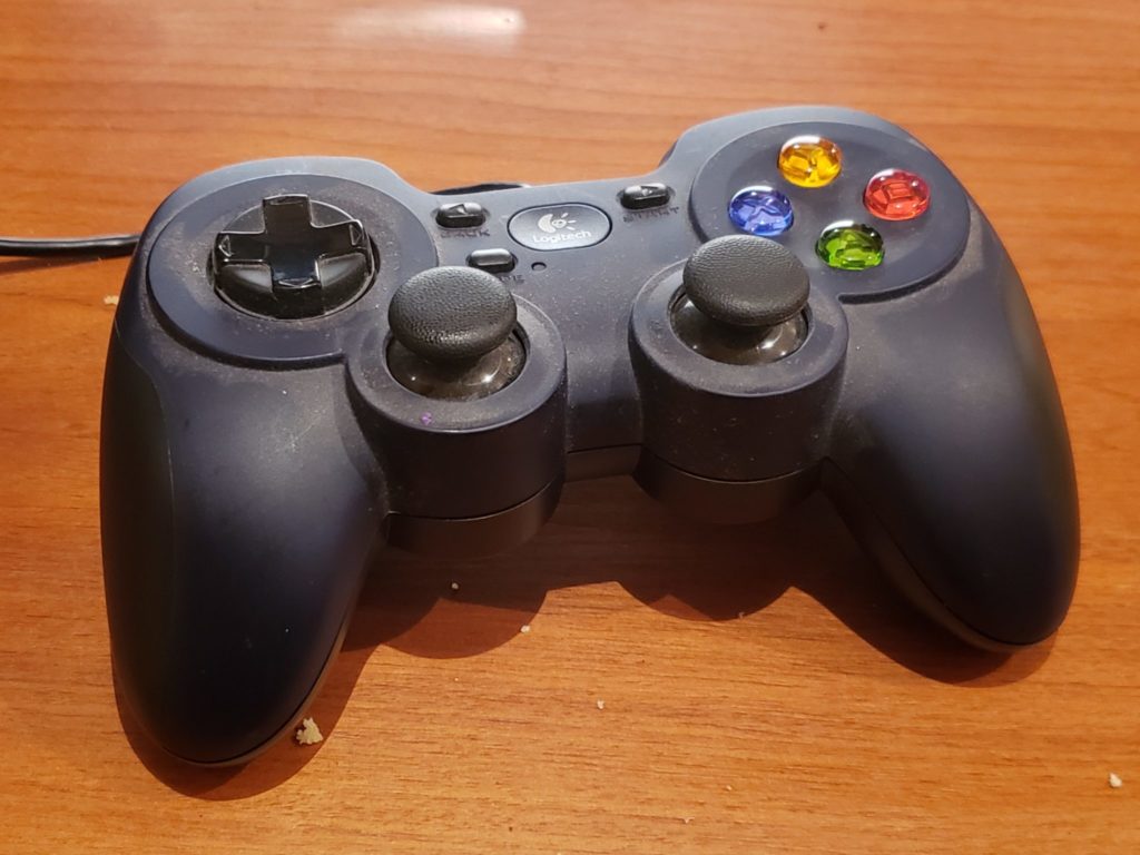
Reading the joystick in Python is super easy using pygame. I ran the demo code toward the bottom of the joystick page as my first step. It showed all axes and buttons working great out of the box with my controller.
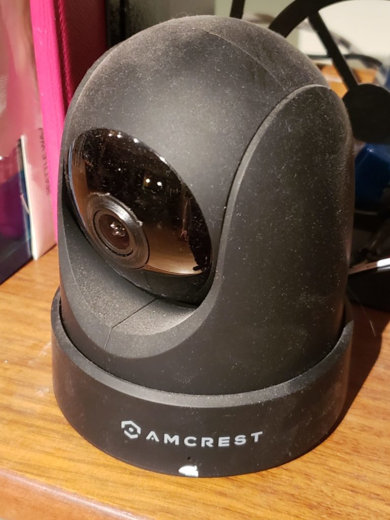
Amcrest cameras support the ONVIF protocol. The python-onvif-zeep package supports sending ONVIF commands from modern Python (I used Python 3.10 for this project).
Specific example code demonstrating how to use the package from Python to send PTZ commands to the camera can be found e.g. here.
Given the ability to read the joystick and the ability to control the camera, we just need to glue it together! So I wrote a 250-line package called joy-ptz-cam that does just this.
The package is pretty limited at the moment but does handle PTZ controls. It pans and tilts with the left joystick and zooms when you pull the right trigger and zooms out when you pull the left trigger. (Note that for this particular camera, zoom is purely software, but on an actual zoom cam it would work the optical zoom).
And there you go I saved myself $500 vs. getting one of those fancy joystick camera controller things.
I have a fancier PTZ ONVIF-compliant camera on order which is the real reason I wanted to try this out on the smaller cam.
A family member upgraded his stereo and offered me his Peachtree Audio Decco as a hand-me-down. I couldn’t say now because my previous hand-me-down has recently become buzzy. But, in order for it to work with my home automation setup, I needed to be able to turn it on and off, switch inputs, and change volume from my Home Assistant home automation system via my Raspberry Pi. I useLIRC for this but there is no remote config for the Decco. So I used the remote and recorded the pulses.
Using irrecord didn’t go that well. The dots were coming in but very slowly. I’d have to sit there for 10 minutes pressing in order to get enough dots for it. So I used mode2 to record raw commands on my pi. Then I hand-edited it to have the right format for a conf file and then ran irrecord -a on it to convert it to actual codes.
Since the LIRC remote DB hasn’t been updated since 2018 and has a few open merge requests, I figured it’d be easier to just post the file here for the next person who needs it. It works great. Here you go.
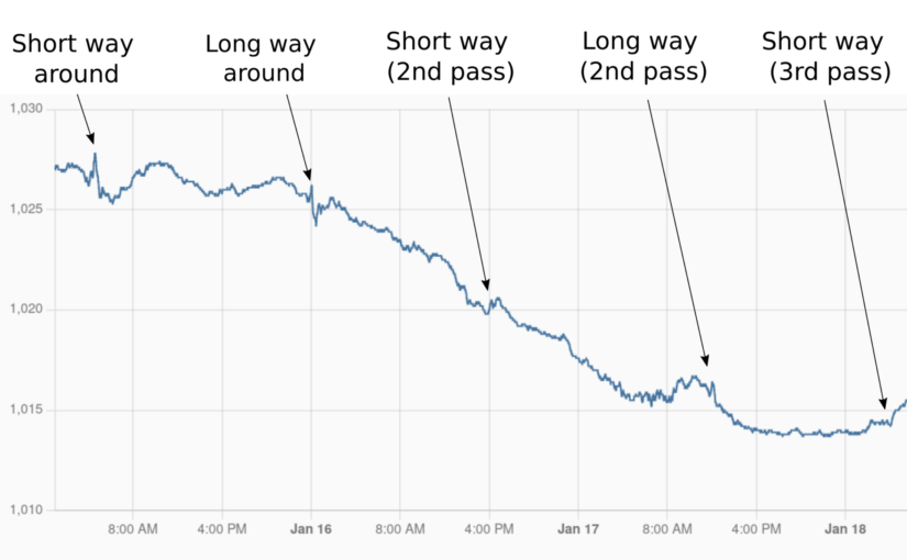
The Tonga eruption on January 14, 2022 sent a big shock wave out in all direction in the atmosphere. I had once read about how the Krakatoa eruption shock wave was measured 7 times going around the world, so I wondered if I could measure it with my weather station. Sure enough, I could!
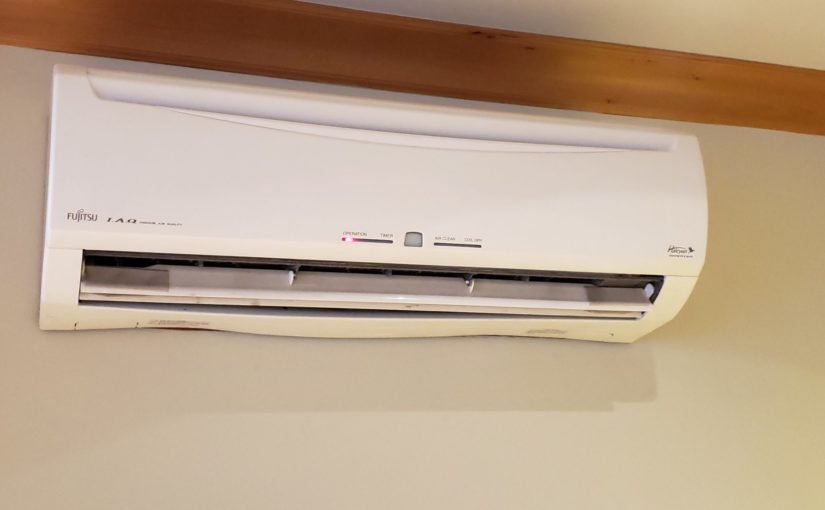
I have some of those mini-split Fujitsu heat pumps in my house that have infrared (IR) remote controls. This post explains how I set up my smart house to be able to automate the heat and air conditioning with a raspberry pi and Home Assistant.
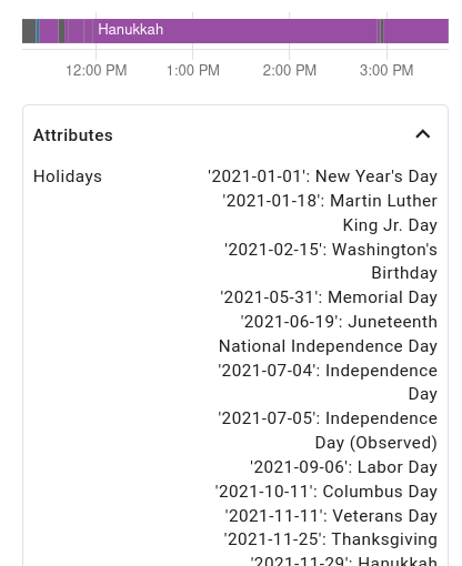
I rigged up some holiday lights that switch between a number of color palettes based on what holiday is coming up next. I used a $25 light strip, a $5 WiFi microcontroller (ESP8266), and Home Assistant to make it all happen.
Setting up the light strip
Using a “NeoPixel”-like addressable RGB light strip is pretty well-covered online these days. I got this waterproof one. I plugged in one of my ESP8266’s and loaded it up with some demo code from the FastLED library. I bought an outdoor waterproof enclosure for the 5V power supply and ran outdoor wires in a small trench over to my fence, where I then used one of these outdoor wire coupler things to both protect the connection and store the ESP8266 itself.
I plugged my Geiger counter’s audio cable into my oscilloscope just for kicks the other day and saw ~9V pulses coming out when it occurred to me that I could easily read those into an Arduino or Raspberry Pi or ESP8266 microcontroller and respond to them. As a demo, I made a hardware random number generator (HRNG) out of a esp8266.
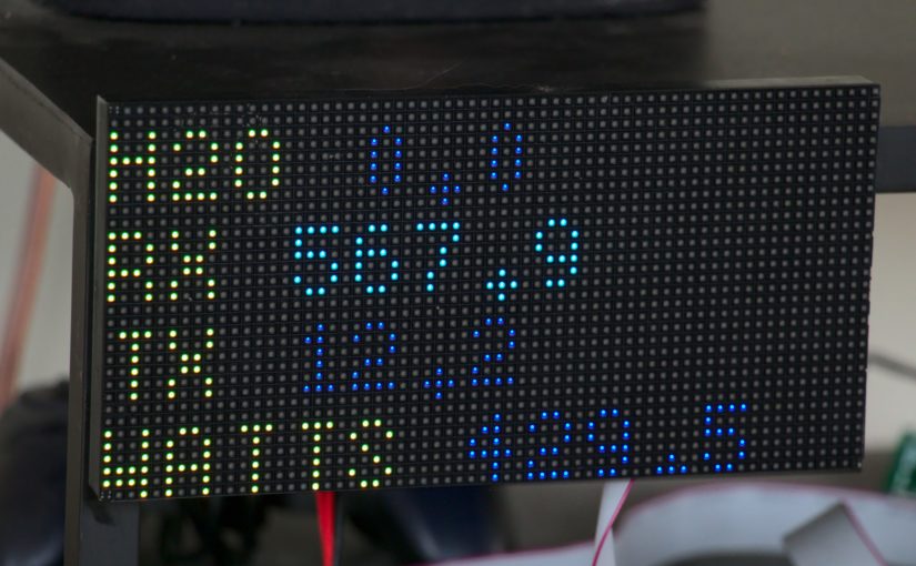
I like the concept of measuring flows and so have sensors on my water main and my electric mains. Naturally, I wanted to add a reading of how much bandwidth I’m using and get it displayed in my living room. I already have the following in place:
A year ago I built 2 DIY weather/air quality sensor packs to monitor the ambient conditions inside and outside, including carbon dioxide (CO₂) levels. Meanwhile, I got a COVID-puppy who sleeps in a covered dog crate. I got to wondering what kind of CO₂ levels that crate got up to at night. So I measured it.
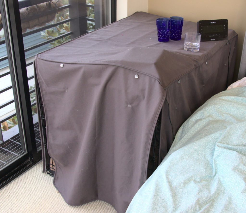
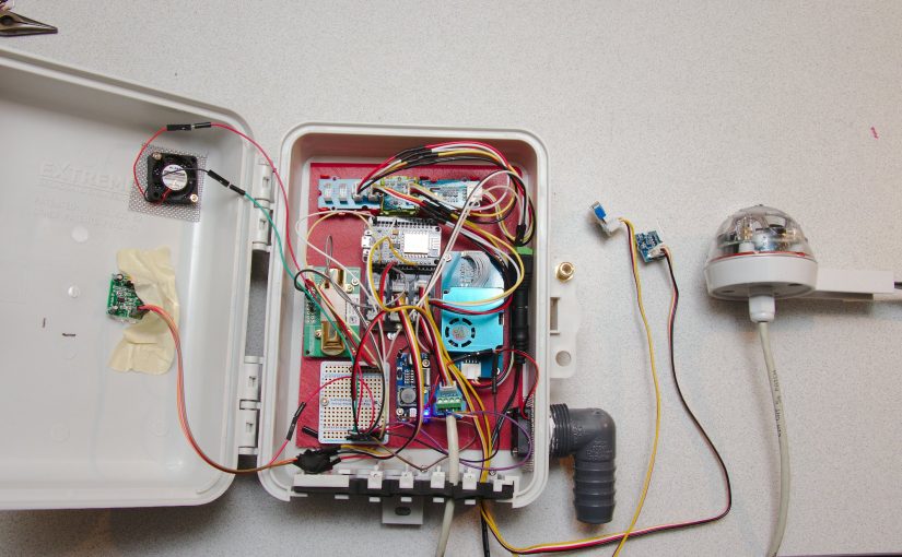
Covered dog crate with air quality sensor pack under it. You can see that there are some gaps.
I just slipped the sensors under the cover like this and let it run all night.
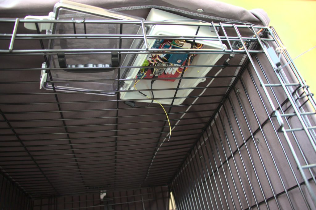
Sensor pack as seen from inside dog crate
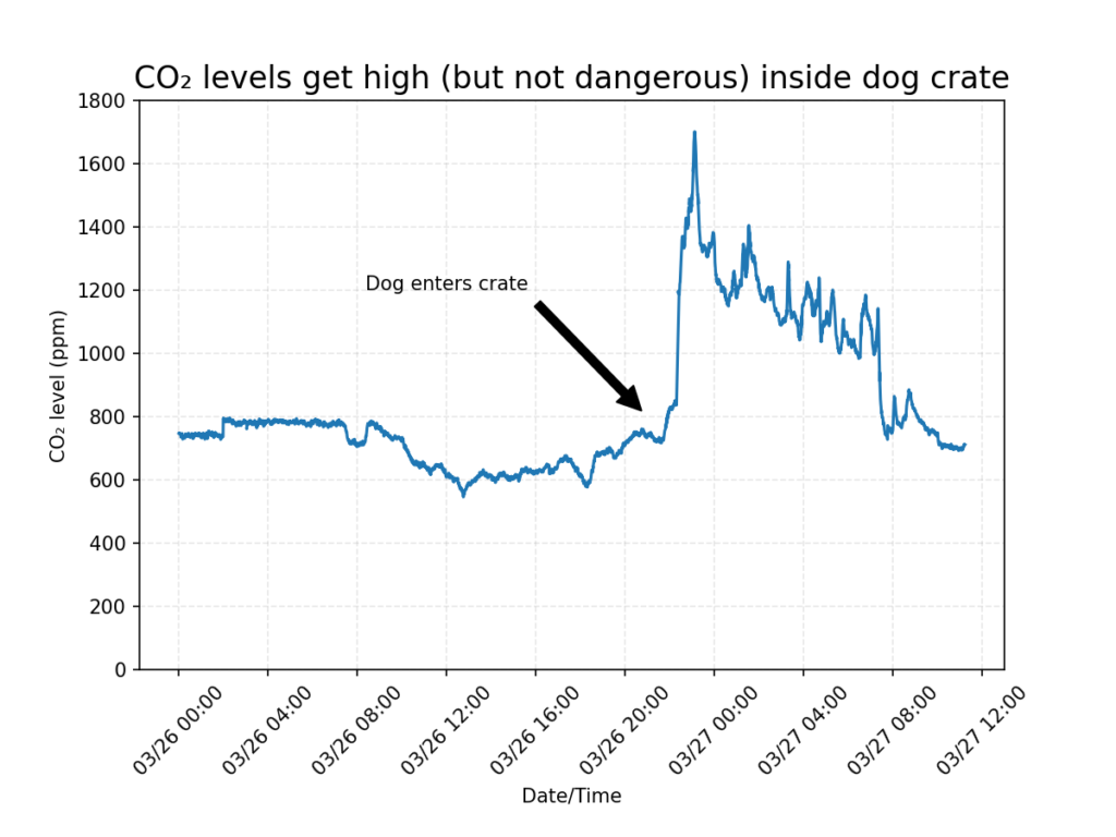
I graphed the readings from the previous day (outside the dog crate) and then inside the dog crate, as indicated with the arrow. As you can see, CO₂ levels did spike quite a bit but did not get above 2000 ppm. For humans, this would be expected to cause drowsiness and complaints about stale air, but would not be harmful.
The actual CO2 readings outside and inside the dog crate overnight.
So in conclusion, a mostly-covered dog crate isn’t deadly, but may be unconformable. I will be opening the back panel at least. I’m a little worried that if the cover was placed so that there were fewer gaps, it could get much higher.
Since the product is no longer sold on Amazon, I am left with putting this product review here. I got a bunch of GE smart toggle switches back in 2016 and installed them in various smarthome builds. Then, just yesterday (2021-03-14), I was (ironically?) installing a different smart switch on the same circuit. I turned the breaker on and off a handful of times while installing/testing the new one. And then I heard a clicking. Click… click…click… click… click… like a metronome with 1 second delay. It was the GE 12727 smart toggle from 2016. It was just clicking and clicking and clicking. At first I thought for sure the new switch was interfering with it somehow so I disconnected it and the clicking continued.
The clicking itself
I guess a 5-year life isn’t terrible, and that one of the issues of going all in on home automation is that complexity generally leads to lower reliability. I can handle replacing the ones in my home, temporarily with the OG dumb switches and then with new upgrades (I’ve been using Inovelli switches recently based in Michigan what what!, which have cool extra features). It’s a lot more problematic when something like this happens at my mom’s house and she has to like call an electrician.
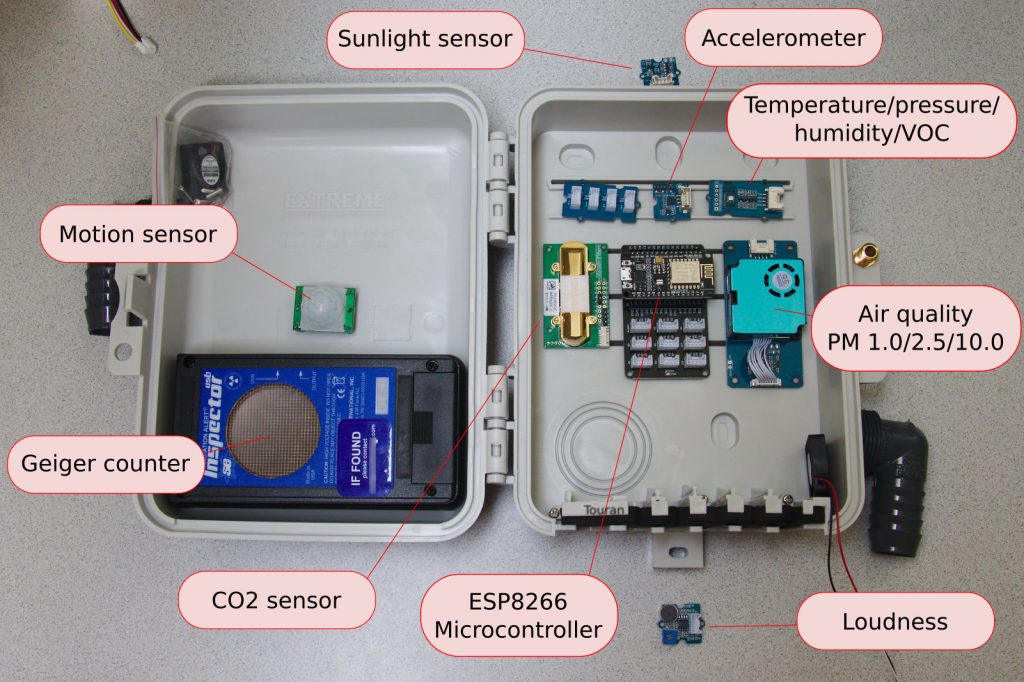
LIS3DHTR 3-axis accelerometer. I read that this one might have the noise and sensitivity characteristics needed to try to measure some seismic activity (I live in Seattle, after all)! Notably I did not research this very seriously so we will see. Note: this chip has three analog-to-digital inputs but they are not available in the Grove package that I got. Prefer Adafruit)!
BME680 gas sensor for Temperature, Humidity, Air Pressure and Volatile Organic Compounds (a rough measure of air quality)
HM3301 Laser PM 2.5 Air quality sensor for measuring particulates in the air at sizes PM1, PM2.5, and PM10. This will be really useful to have one outside and one inside during fire season so I can see how dangerous the air is outside and how well my air filters are doing inside.
Grove Loudness Sensor for keeping up with traffic noise, fireworks, landscaping, air traffic, etc.
The ESP8266 Microcontroller. I absolutely love the ESP8266 for being the brains of things like this. I had used one for my doorbell sensor, my mom’s boiler controller, and various other things. Programming this to read all these sensors is a major part of this project.
MH-Z14A NDIR carbon dioxide sensor (up to 5000 ppm). This is more interesting on the indoor unit than the outdoor unit, but fun nonetheless
Geiger Counter with USB interface. I had to reverse engineer the protocol coming out of this USB port and was able to do it using pyusb but that’s another post in itself. Unfortunately, I don’t think I can actually read this USB port too easily on the ESP8266 so I might have to slap a Raspberry Pi in here, or some other USB interface. This is a big TBD.
(Not pictured, see below or rain sensor post): Infrared rain sensor from Hydreon in MN. This is actually a sweet sensor. It shoots IR light around the dome and when water hits it, refraction of IR changes and the response at the receiver can pick up even a single raindrop. Garsh-darned epic!
As you can maybe see, I got most of these sensors with I2C interfaces from Grove, which has a really nice ecosystem with easily-interconnectable sensors. This is my first experience with the Grove ecosystem, and I love it. Very clean. Note, however, that I2C is not good for off-board sensors (so maybe not a great choice for the sunlight sensor which should be placed higher up).
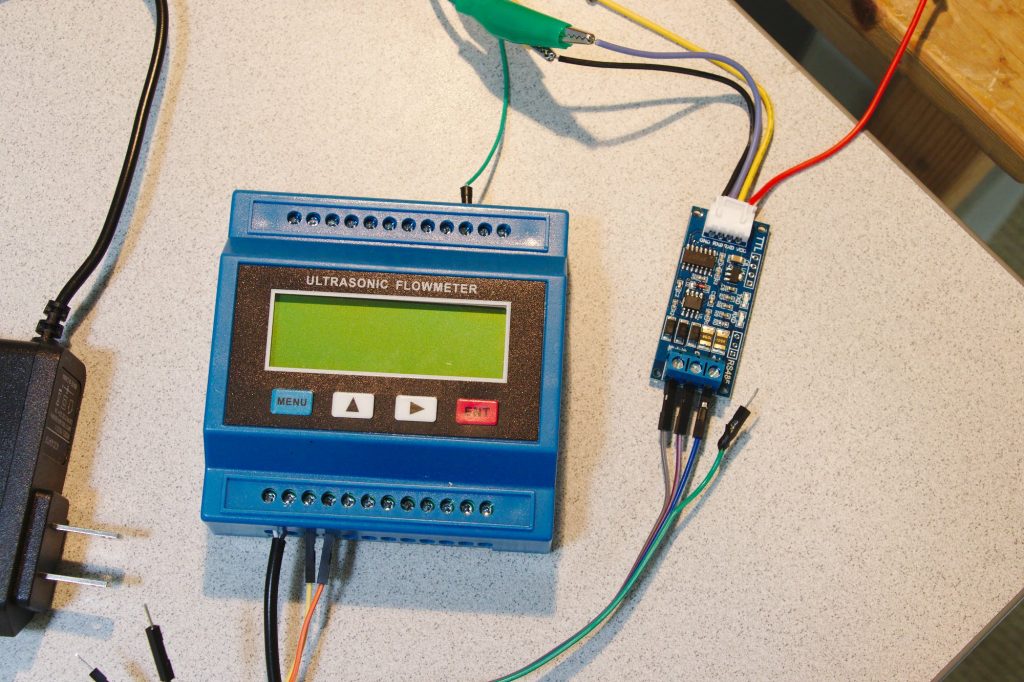
I had a flood in the garage the other day and realized how great of an investment my flood sensor had been, saving me literally weeks of time and thousands of dollars in repairs. As I considered buying more flood sensors to cover more parts of the house, the thought to put a flow meter on the main water inlet to the house popped into my mind. It’s not quite as clear of a signal as a flood sensor, but if I detect flow when everyone is asleep or when on vacation, I can be sure that something is going wrong and have Home Assistant give me an alert.
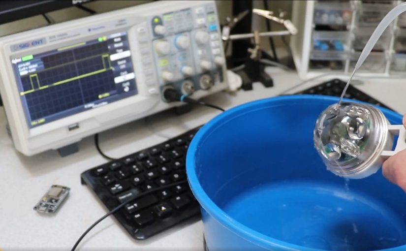
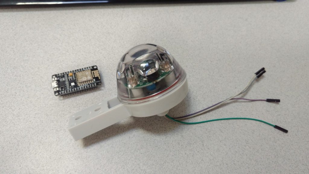
I’ve been working on a home-brew weather station and was looking into rain sensors when I discovered that you can get infrared (IR) rain detectors. A company in Minnesota sells one called the Hydreon RG-11. They shoot pulses of IR light around a plastic dome and monitor them on the other end. When rain hits the dome, the refraction changes and the pulses received are perturbed. This is nice because it’s very simple and has no moving parts. I figured I’d be able to find a way to read it into my weather station.
I had a bad experience with push-to-connect pipe fittings between my hot water heater and my hydronic heating system and wanted to share with you what happened.
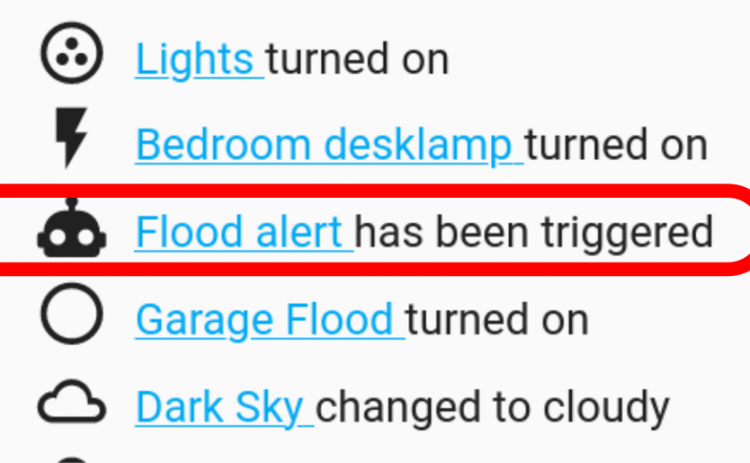
On Saturday morning at 4:19 am I was fast asleep. But then I jolted awake as the bedroom lights flashed on and a slightly robotic voice proclaimed:
“FLOOD ALERT! FLOOD ALERT. IN THE GARAGE! FLOOD!”
“Huh!”, I thought. “I wonder why that thing is going off?”
Some friend of a friend was over a few months ago (before the quarantine) and saw my Galileo Thermometer and explained to everyone how he thought it worked. He was wrong. So I figured, ok the world needs a better explanation of how these these things work. So I made this video.
The force balance on each float is gravity down, buoyancy up. The mass and volume (and therefore the density) of each float does not change as a function of temperature. The density of the clear surrounding fluid does go down with temperature. Because of this, the mass of clear fluid displaced does go down with temperature, and so the buoyant force does decrease as it heats up. When the upward force decreases, the floats drop down as gravity takes over.
To prove it, I made this video where you can clearly see the clear fluid rising as the thermometer heats up.
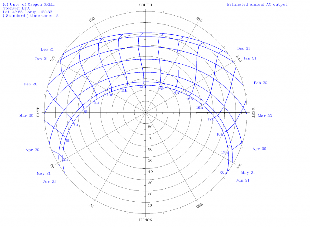
I happened upon a polar sun path chart a while back and really thought it was a great graphic. It shows where the sun goes each day as a function of the seasons. Behold:
The polar Sun path chart for Seattle, WA
For Seattle, you can see at the top that the sun rises in the SE, peaks at 20° above the horizon, and then sets at 4:30pm on the winter solstice. Ugh. But in the summer, it’s up from before 4am to after 8pm, and peaks above 60° . You can make one of these plots for your area over at the University of Oregon’s Solar Radiation Monitoring Lab.
I liked this plot so much that I wanted to take it to the next level and see where the sun is live. In my experience with Python, I’ve grown to expect there to be sweet libraries that can compute stuff like that. Sure enough, there are a few. First, I found pysolar, which is really straightforward, fast, and simple. A few lines of code and I was up and running.
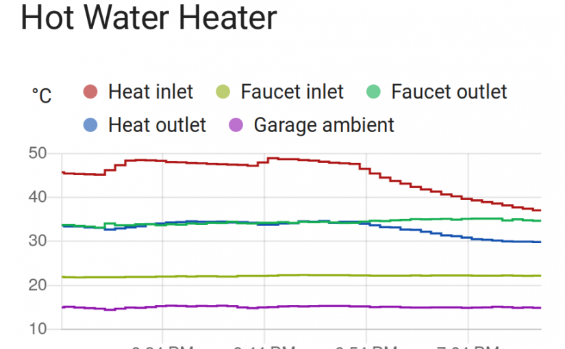
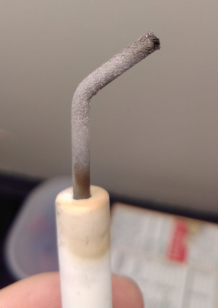
I’ve got one of those hydronic home heating systems where hot water from the hot water heater gets pumped to radiators around the house in addition to heating up water for faucets. A few days ago it died on me and threw an error code indicating something was wrong with ignition. I took a look at the igniter and found that it was full of an oxide layer.
After sandpapering it, it worked great, but I ordered a spare for when this inevitably happens again. Along the way, it occurred to me that it’d be kind of fun to have instrumentation on my hot water heater. I just got it up and running.
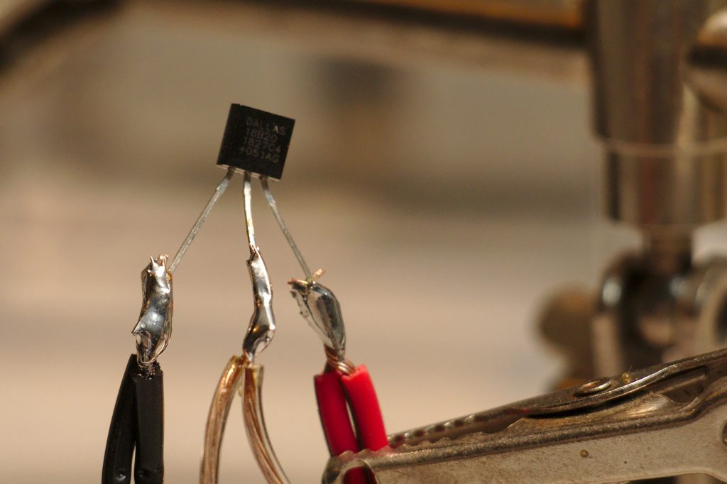
Way back in my first post about hot tubs, I used OneWire sensors called Dallas 18B20s (datasheet) with an Arduino 2009. They worked great at hot water temperature, so I decided to try them out again. This time, rather than using an Arduino, I’m using a ESP8266 microcontroller. These are cheap and have Wi-Fi, so I can easily get the data into my home assistant setup, just like I did with my mom’s furnace, my doorbell, and other stuff.
Step one is to solder a bunch of sensors together. I wanted to get readings on all the different pipes going into and out of my hot water heater. I went down there and measured how much space I’d need between each sensor. Then I soldered them up. Notably 18B20s can work in “parasite mode” with just two wires, but there are problems with parasite mode on ESP8266’s, and in prototype testing I was unable to get that mode to work. So I just wired them up to 3 wires. This tutorial is a good one for wiring up these sensors.
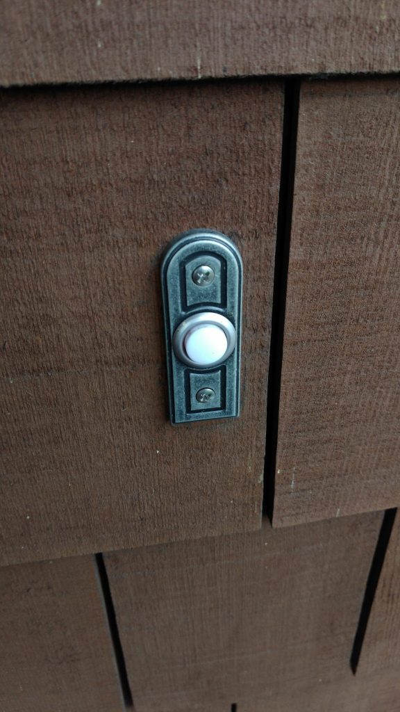
I live in tall and skinny house with a loft on the upper floor. I can’t hear the doorbell going off when I’m up there, especially if I have music playing. This post is about how I extended the range of my doorbell by hooking a sensor up to it that communicates over Wifi to my smart-home, which then plays a doorbell tone over my speakers throughout the house.
I already have a reasonably capable smart home based on Home Assistant, so I challenged myself to do this in the cheapest, least intrusive way possible. In the end, I did this with a $7 part and without changing any of the wiring in my existing doorbell (I just had to connect 2 extra wires to the existing transformer).
It’s that spooky time of year again, but this time it can be extra spooky with the help of home automation.
Motion-activated jumpscare on TV
One classic spooky thing to do is have a TV do something scary when people walk by. This is easier than ever on any TV now that everyone has Raspberry Pi with HDMI output and z-wave (or other) motion sensors everywhere. Check this out: