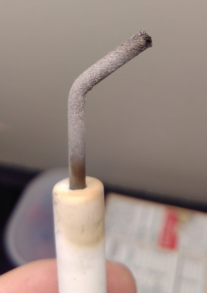
I’ve got one of those hydronic home heating systems where hot water from the hot water heater gets pumped to radiators around the house in addition to heating up water for faucets. A few days ago it died on me and threw an error code indicating something was wrong with ignition. I took a look at the igniter and found that it was full of an oxide layer.
After sandpapering it, it worked great, but I ordered a spare for when this inevitably happens again. Along the way, it occurred to me that it’d be kind of fun to have instrumentation on my hot water heater. I just got it up and running.
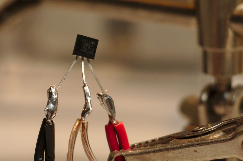
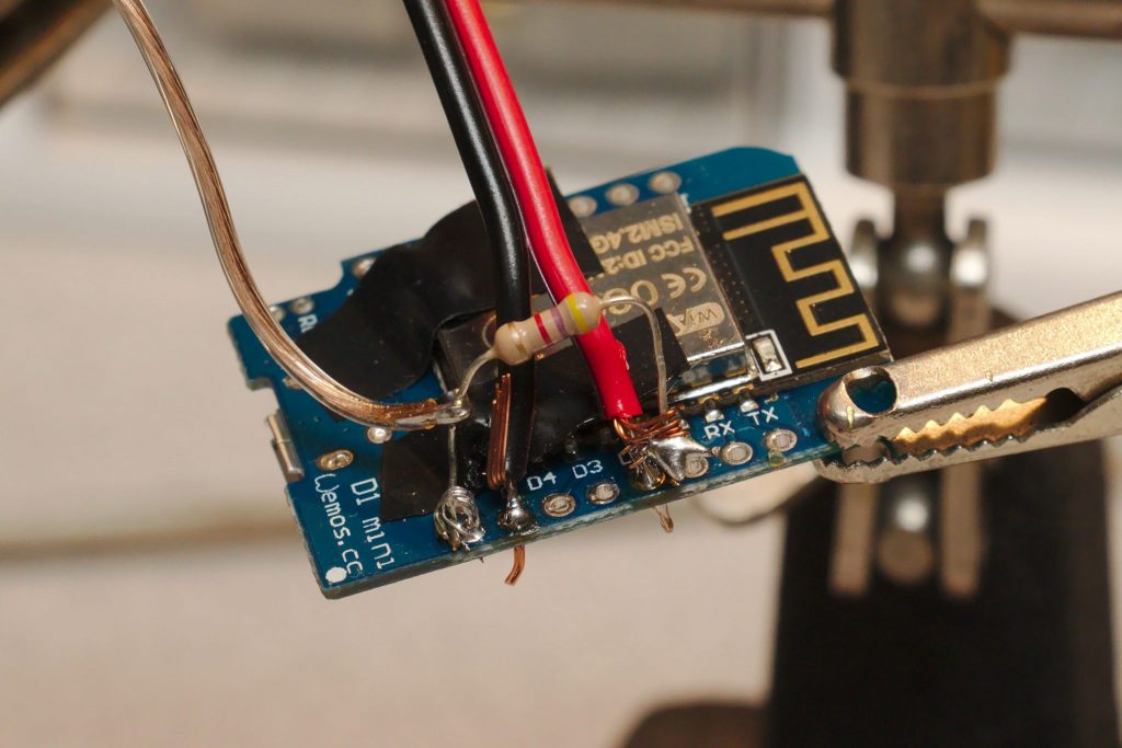
Way back in my first post about hot tubs, I used OneWire sensors called Dallas 18B20s (datasheet) with an Arduino 2009. They worked great at hot water temperature, so I decided to try them out again. This time, rather than using an Arduino, I’m using a ESP8266 microcontroller. These are cheap and have Wi-Fi, so I can easily get the data into my home assistant setup, just like I did with my mom’s furnace, my doorbell, and other stuff.
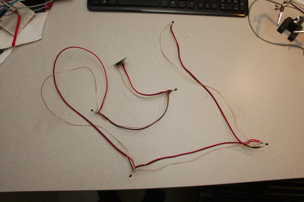
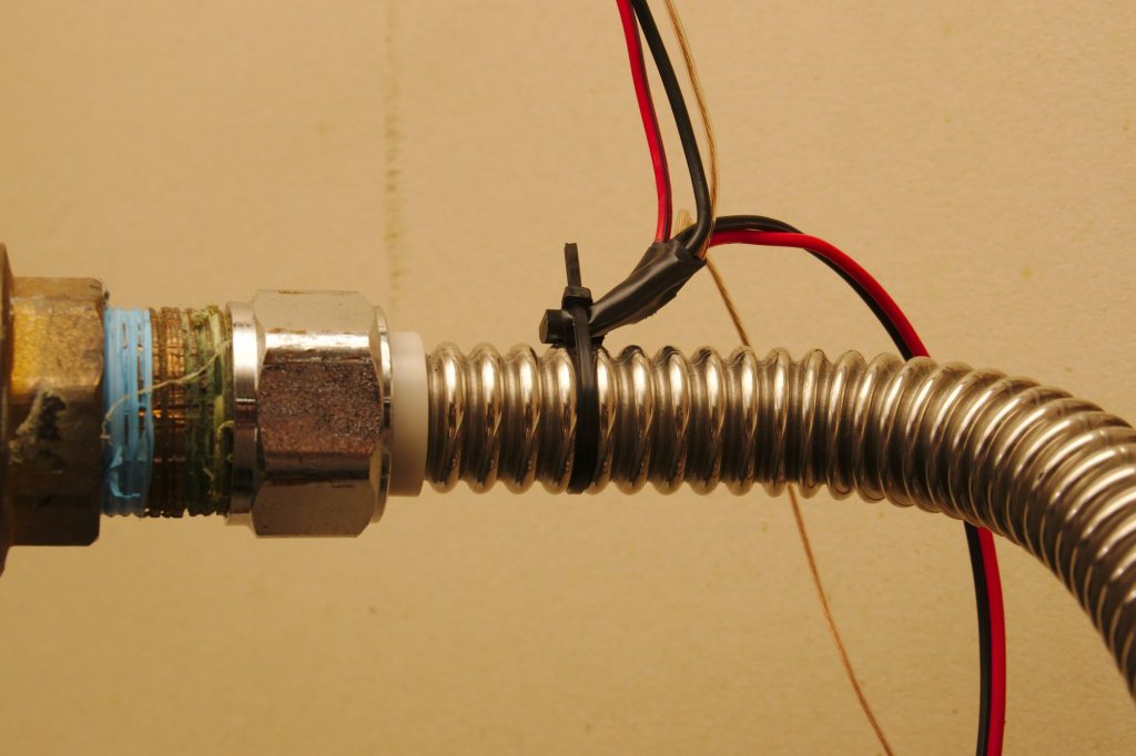
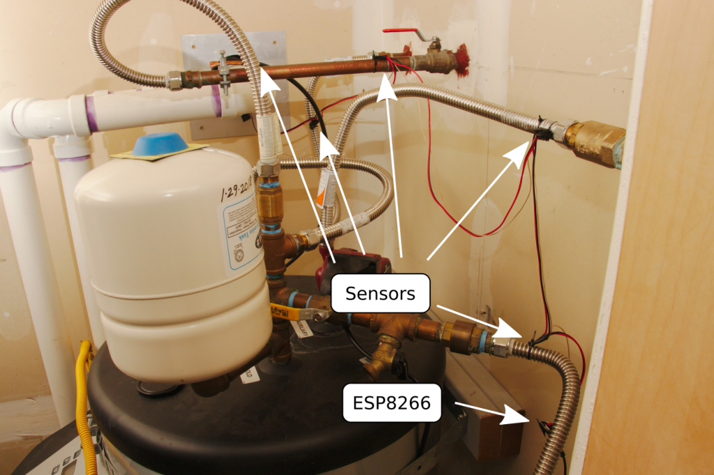
Step one is to solder a bunch of sensors together. I wanted to get readings on all the different pipes going into and out of my hot water heater. I went down there and measured how much space I’d need between each sensor. Then I soldered them up. Notably 18B20s can work in “parasite mode” with just two wires, but there are problems with parasite mode on ESP8266’s, and in prototype testing I was unable to get that mode to work. So I just wired them up to 3 wires. This tutorial is a good one for wiring up these sensors.
For software, I already have a MQTT server up and running from my home automation setups, so the easiest thing is to just transmit the data via Wi-Fi/MQTT to my server and then receive/process it with Home Assistant.
The ESP8266 code is pretty straightforward. It connects to Wi-Fi and MQTT and then just sits around for a pre-determine delay (60 seconds) after which it reads the sensors and transmits them. Here it is:
/*
Hot water heater temperature monitoring station.

This reads a few temperature sensors at various points
on a hot water heater (or whatever) and transmits
them back to some place where they can be read and
processed (like a Home Assistant system).

Temperature sensors used here are DS18B20's in non-parasite mode.
These have good temperature resolution up to hot water temperatures.
*/

#include <OneWire.h>
#include <DallasTemperature.h>

#include <ESP8266WiFi.h>
#include <ESP8266mDNS.h>
#include <PubSubClient.h>

#define wifi_ssid "Wifi SSID"
#define wifi_password "Actual password"

#define mqtt_server "dummy-mqtt-server.com"
#define mqtt_will_topic "home/status/garage"
#define mqtt_user "user"
#define mqtt_password "password"

#define ONE_WIRE_BUS D2

OneWire oneWire(ONE_WIRE_BUS);
DallasTemperature sensors(&oneWire);
WiFiClientSecure  espClient;
PubSubClient client(espClient);

int numDevices;
String baseTopic = "home/garage/";
unsigned long previousMillis = 0;
const long intervalMillis = 60000; // how often to update

DeviceAddress tempDeviceAddress;

void setup(){
  pinMode(D2, INPUT);
  pinMode(D2, OUTPUT);
  sensors.begin();
  Serial.begin(9600);
  Serial.print("Greetings from the water heater.");
  setup_wifi();
  setup_mqtt();

  Serial.print("Initializing devices...");
  numDevices= sensors.getDeviceCount();
  Serial.print("Found ");
  Serial.print(numDevices, DEC);
  Serial.println(" devices.");

  for(int i=0;i<numDevices; i++){
    if(sensors.getAddress(tempDeviceAddress, i)){
      Serial.print("Found device ");
      Serial.print(i, DEC);
      Serial.print(" @: ");
      printAddress(tempDeviceAddress);
      Serial.println();
    } else {
      Serial.print("Found phantom device at ");
      Serial.print(i, DEC);
      Serial.print(" but could not detect address. Check power and cabling");
    }
  }
}

void loop(){
  unsigned long currentMillis = millis();

  if (!client.connected()) {
      reconnect();
  }
  client.loop();
  ArduinoOTA.handle();

  if (currentMillis - previousMillis >= intervalMillis) {
    previousMillis = currentMillis;
    readSensors();
  }

}

void readSensors() {
  String fullTopic;
  String value;
  String address;

  sensors.requestTemperatures();

  for(int i=0;i<numDevices; i++){
    if(sensors.getAddress(tempDeviceAddress, i)){
      address = (char *) tempDeviceAddress;
      Serial.print("Temperature @: ");
      Serial.print(i,DEC);
      float tempC = sensors.getTempC(tempDeviceAddress);
      printAddress(tempDeviceAddress);
      Serial.print(" °C: ");
      Serial.println(tempC);
      fullTopic = baseTopic + i;
      value = String(tempC);
      client.publish(fullTopic.c_str(), value.c_str(), true);
    }
  }
}

void printAddress(DeviceAddress deviceAddress) {
  for (uint8_t i = 0; i < 8; i++){
    if (deviceAddress[i] < 16) Serial.print("0");
      Serial.print(deviceAddress[i], HEX);
  }
}

void setup_wifi() {
  espClient.setInsecure();  // required since bearssl
  delay(10);
  Serial.println();
  Serial.print("Connecting to ");
  Serial.println(wifi_ssid);
  WiFi.mode(WIFI_STA);
  WiFi.begin(wifi_ssid, wifi_password);
  while (WiFi.status() != WL_CONNECTED) {
    delay(500);
    Serial.print(".");
  }
  Serial.println("");
  Serial.println("WiFi connected");
}

void setup_mqtt() {
    client.setServer(mqtt_server, 8883);
    client.publish(mqtt_will_topic, "1", true);
}

void reconnect() {
  int retryCount=0;
  while (!client.connected()) {
    Serial.print("Attempting MQTT connection...");
    if (client.connect("Garage", mqtt_user, mqtt_password, mqtt_will_topic,
                        1, 1, "0")) {
      Serial.println("connected");
      client.publish(mqtt_will_topic, "1", true);

    } else {
      Serial.print("failed, rc=");
      Serial.print(client.state());
      Serial.println(" try again in 3 seconds");
      delay(3000);
      retryCount++;
      if (retryCount>20) {
        Serial.println("Goofed up. Restarting.");
        ESP.restart();
      }
    }
  }
  Serial.print("MQTT connected.");
}
Then the setup in Home Assistant configuration is just a few MQTT sensors. To figure out which sensor was which I had to put my finger on them individually to see which one heated up first.
# Hot water heater sensor order from esp is 3 2 1 0 4
  - platform: mqtt
    name: Heat outlet
    state_topic: "home/garage/3"
    device_class: temperature
    unit_of_measurement: '°C'
  - platform: mqtt
    name: Heat inlet
    state_topic: "home/garage/2"
    device_class: temperature
    unit_of_measurement: '°C'
  - platform: mqtt
    name: Faucet inlet
    state_topic: "home/garage/1"
    device_class: temperature
    unit_of_measurement: '°C'
  - platform: mqtt
    name: Faucet outlet
    state_topic: "home/garage/0"
    device_class: temperature
    unit_of_measurement: '°C'
  - platform: mqtt
    name: Garage ambient
    state_topic: "home/garage/4"
    device_class: temperature
    unit_of_measurement: '°C'
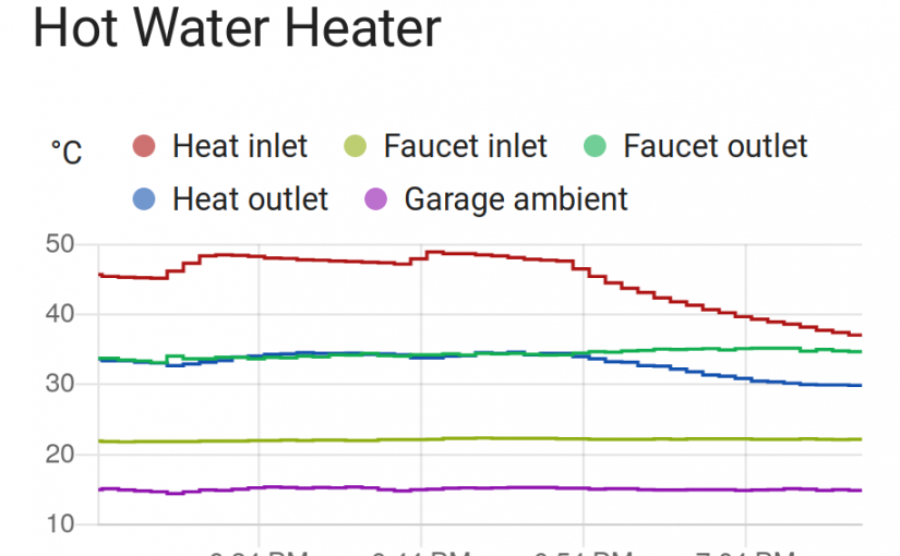
With that configured, I went to the front end and added a new History Graph card from Lovelace and choose the new sensors by name. An hour later, the data looked like this:
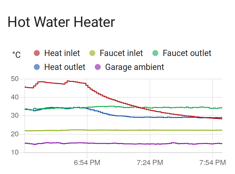
I love it. And of course, I added an e-mail alert when the faucet outlet temperature drops below 30 °C so I’ll be able to swap out the igniters before the thing cools all the way down.
It’s a “water heater”. Not a “hot” water heater. If the water was hot we wouldn’t need to hear it now would we?.
Electric heaters heat with electricity. Hot water heaters heat with hot water. It’s apparently a regional thing:
If the water reaches 30°F at your faucet you lose. It is frozen and you have no hot water or cold. You will have a host of problems. As most forced water heat systems run a 180°F the chance of scalding is a real concern. I hope you have a mixing valve installed. Over a period of time I would not want the water in my heating system to be anyway connected to my potable water system. Most codes put limits on this type of application . As a master plumber I fail to see the reason for this set up. I can put my hand under the water or use a thermometer to measure it. Interesting but not necessary. Good luck.
Just edited it to say 30 °C. Certainly 30 °F would be more problematic. I have a thermometer reporting at my mom’s house for when she goes away for a few days and it’s -20 °F outside. The furnace died once in this situation and I called a plumber before any pipes froze thanks to sensors like these.
As for this system, I’m really doing it just for fun because I like putting sensors on things and seeing graphs. But I also want indication when the spring-activated check valve fails or when the mixing valve fails (as both have failed in the past). This will tell me nicely when those happen.
This is great inspiration for a project that I am working on to measure the temperature in an electric water heater. Thank you for sharing!