Sending and receiving text with Morse code light pulses across the room (or to your neighbor) is a fun and cheap project you can do on a Raspberry Pi or Arduino or any other microcontroller. This post explains how I did it, and how you can do it too.
Hardware
The hardware is simple and cheap. Here’s my parts list:
- Raspberry Pi B+ as the controller. This does the sending, receiving, and signal processing.
- Photoresistor – Just a little guy that has variable resistance based on how much light is hitting it
- A 220 Ohm resistor – to make a voltage divider with the photoresistor for reading the input signal
- MCP3008 10-bit Analog-to-Digital Converter (ADC) – Since the RPi doesn’t come with an ADC, this is required for converting analog voltage from the photoresistor into a signal I can process on the RPi.
- Laser module – to transmit with laser light. I got one from sunfounder.com for like 3 bucks.
- Breadboard, wires
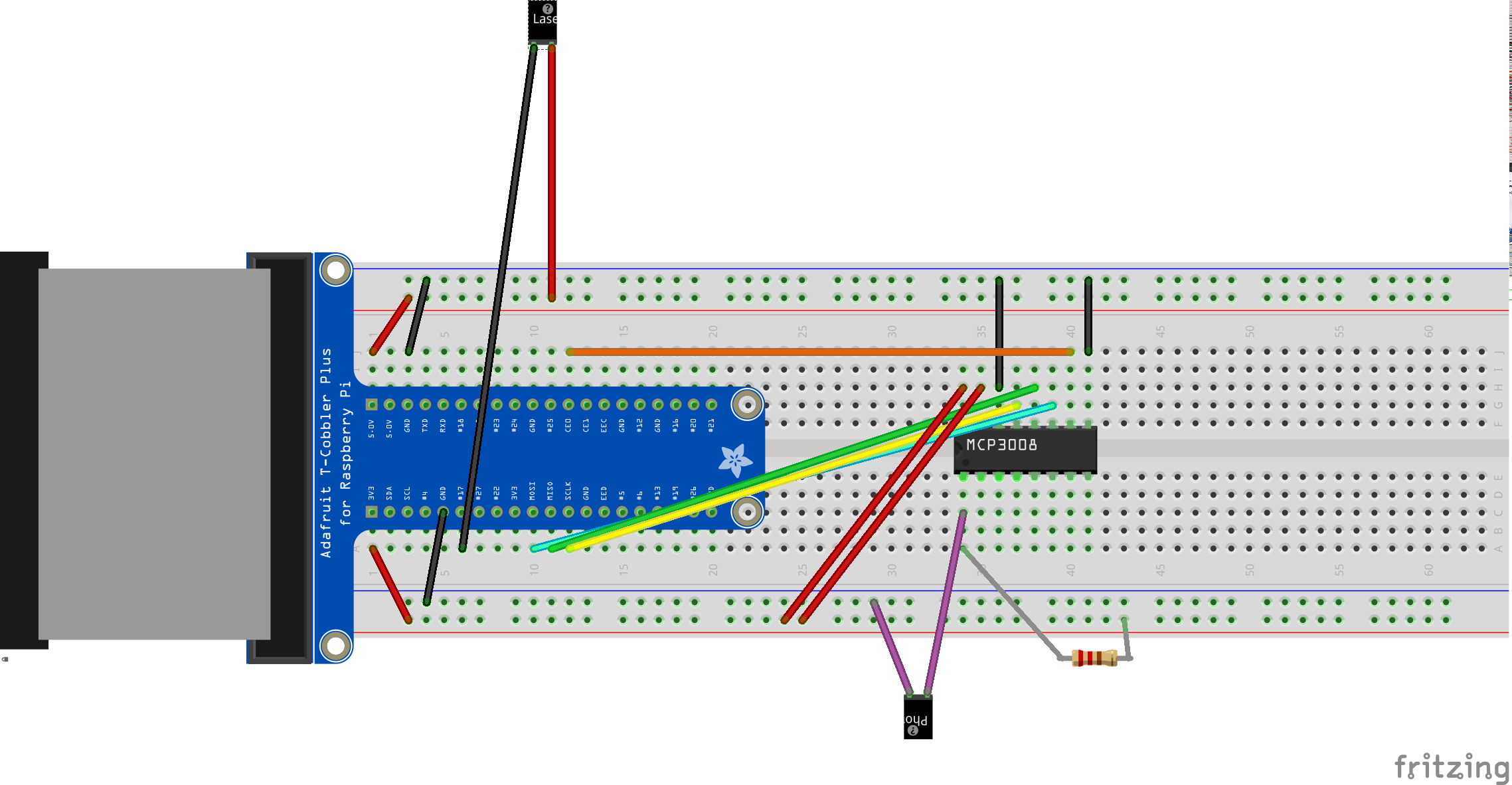
You can learn how to use the ADC at this Adafruit tutorial. I decided to talk to the ADC with the RPi’s hardware SPI interface, which I had already enabled. I wanted to be able to go very fast. (You can alternatively do SPI off of GPIO ports with software, if you prefer.) The laser just hooks directly between a GPIO and +5V. Here’s the layout:
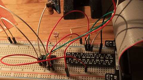
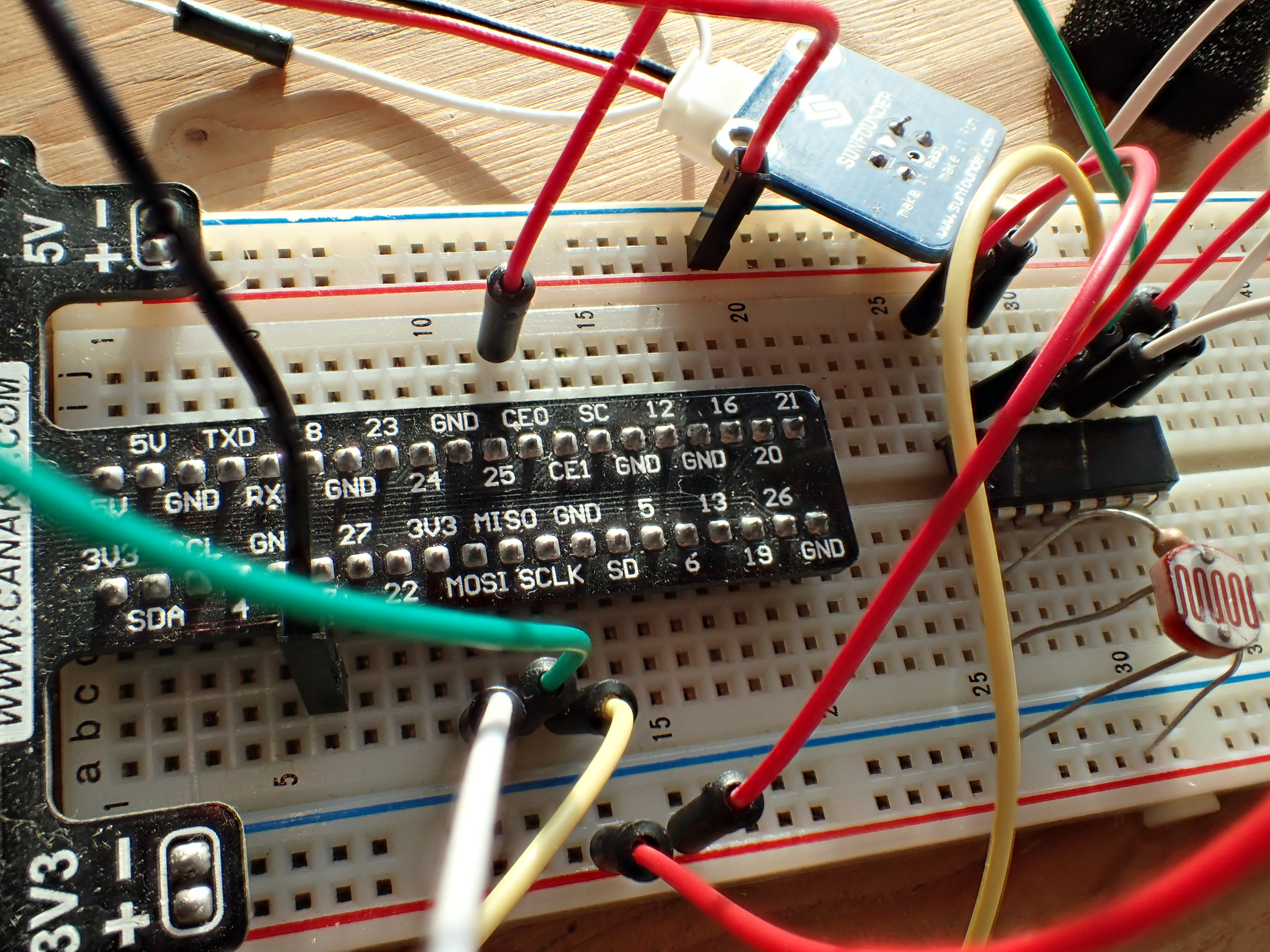
And what it actually looks like:
I played around with a flashlight and some different sized resistors on that photoresistor voltage divider. The 220 Ohm one gave me a good reading on the ADC with my particular photoresistor. Depending on your photoresistor, different resistances may work better for you.
Software
This project is mostly software. It’s all available for you to download.
Blinking the laser
I had a little head start in Morse code thanks to the work I had previously done on a small Morse code library and training program. Starting from my program that beeps the speaker with code, it was pretty simple to make a new subclass that would flip the GPIO pin hooked to the laser on and off for whatever text I wanted to send. The code that blinks the laser is available on my github.
Receiving the light pulses
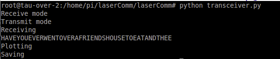
This was the hard part, but it’s not too bad. Reading the signal in from the ADC was fairly straightforward. The code to do that is here. Right now, it just reads for 30 seconds, hard-coded. Future versions would have some kind of end-of-message detection. The timing was a little funny as well. Python’s time.sleep() doesn’t work too well on the 10-thousandths-of-a-second time-frame so I used clock. I think there’s a lot of room for improvement here, so feel free to update my code if you get into this. So far I just have this proof of concept.
Processing the signal
Now the fun part: the signal processing code! I did initial testing by hand and did a little work to try to get the system to be resilient against imprecise dit and dah timings. But when receiving from the computer-controlled laser, timing is pretty precise. I start with a signal of at least a few seconds (containing a few dits and a few dahs) and throw it into a histogram to find out where the tone-on signals are and where the tone-off signals are. I decided that the tone-off signals are the best to look at because the ambient light condition is pretty constant, whereas the tone-on signal depends on how completely the photoresistor is covered. This could very with hand-shake or (over longer distances) atmospheric conditions.
The design of my voltage divider means high signals come when it’s just ambient light, so we’re looking for those. This histogram has a few bins (currently 6) and the top bin sets the bounds for a signal being considered “off.”
With that, we loop through all the samples and locate the indices where the signal crosses the on/off thresholds. I found that you have to filter very short crossings sometimes (~2-4 samples wide where a normal dit is like 200 samples wide) in order to get good results over longer strings of text. Then you do a quick check to see if the signal was on or off when receiving began and you just write down the bounds of when the signal is considered on and off for each individual pulse. The results from one of my tests look like this:
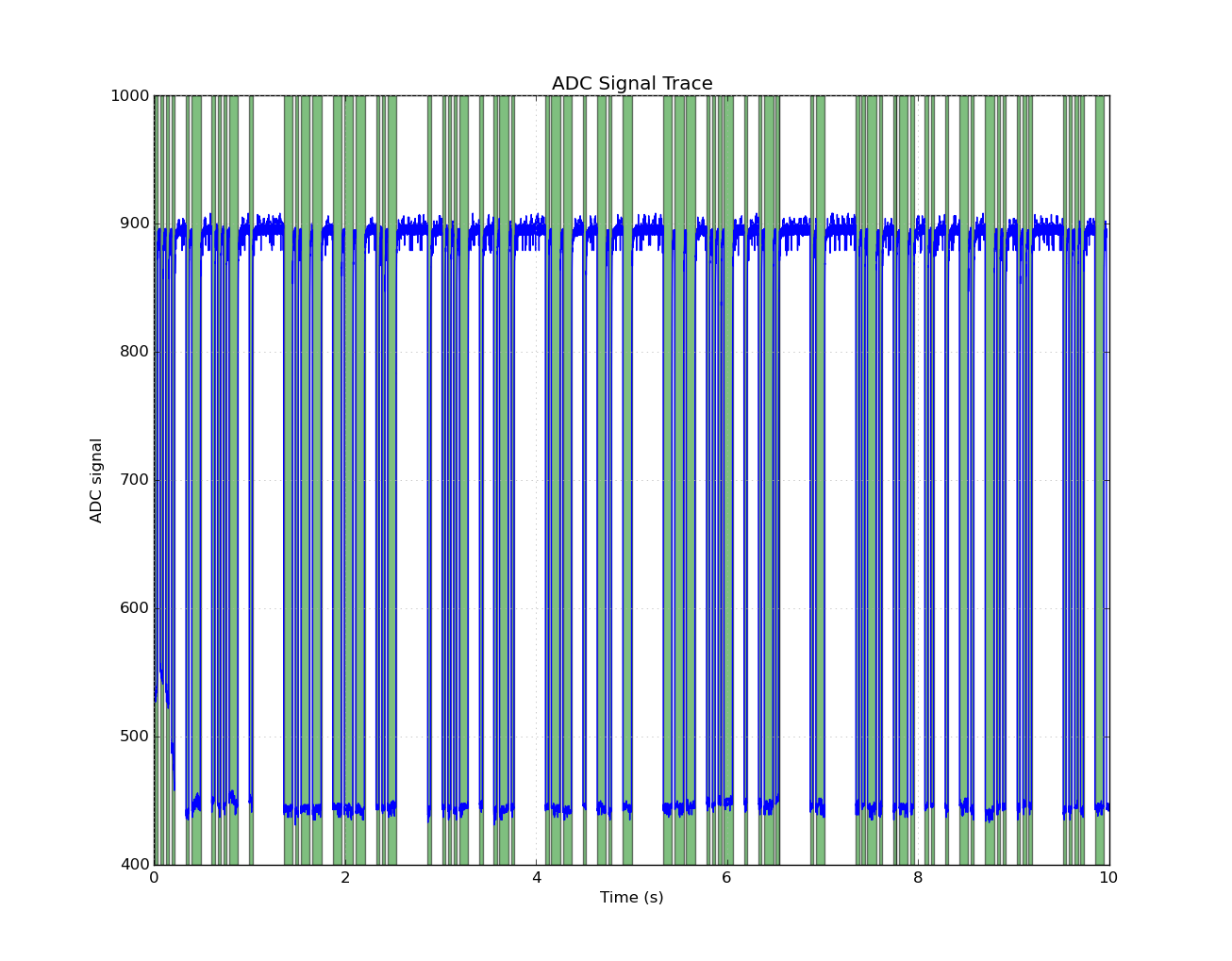
You can really see that we have nice clusters of dits and dahs in the green bands at this point. So we’re in good shape! The last step is to run another histogram, this time on the durations of the on-pulses. Personally, I’m not good enough at Morse code (aka CW) to have very consistent timing by hand, so the variety is large. But, again, with computer control, it’s pretty easy to detect what’s a dit and what’s a dah. I just take the average of all things in the short-duration bins and call that my average dit duration. If 3 average dits go by without a new signal, then I call that a letter and pass it to morsecodelib to decode.
“Full duplex” operation
I have one Raspberry Pi right now so I can only have it talk to itself. So I needed it to transmit and receive at the same time, in full-duplex. This works fine with threading, as seen in the transceiver module. But it’s in “quotations” because you can’t read the received message until the hard-coded timeout elapses. Adding running histograms and more real-time message printouts is probably the next feature I want to add to this thing.
 Boom.
Boom.
Future work
Since I did all this a lazy Sunday (and rushed to get it working before the end of the weekend), there’s still lots to be done, including:
- Add real time reception printouts
- Add a more usable user interface
- Add beginning and end of message indicators of some sort
- See how fast I can reliably go (I got up to 40 WPM so far)
- See how far apart I can reliably go. At least try it out with a neighbor and actually send messages to another device
- More integration with morsecodelib to have receiver optionally play sounds while decoding
- Put proper spaces between words
I hope you liked this project. Let me know if you have suggestions. If you want to work on the code on github, feel free!
UPDATE: This post was found by an artist in Europe who I then collaborated with to do a few art installations! See my post: Helping an artist with a Morse code protest chant installation in Denmark
Interesting; neat to see this. One idea I had for a smartphone application would be to transmit and receive/recognize Morse code.
Looks like since I made an initial search for it and found nothing, someone made it reality: http://www.makeuseof.com/tag/danger-phone-signal-morse-code-mobile-phone/.
I am not able to execute the same. Transceiver.py runs but gives me an error “avg = a.mean(axis)” RunTimeWarning: Mean of empty slice. and also invalid value encountered in double_scalars.
What to do. I am stuck big time.
I think that’s just a warning from the numpy library and it probably happens when there’s no signal received. Is the laser transmitter blinking at this time at all?
Yes it is. But whatever i try not able to execute. Everything is in shape. Even if it executes I am getting different values or ‘&’. Different values in the sense ‘T’ or ‘U’ thats it. Just this much..Not the full sentence.
I would like to know if you have and distance test results to share.
Great project for learners and teachers.
Thank you,
PiRexTech
I do not have data on that. That could be pretty fun. I have no doubt that it would work any line-of-site distance in my small house so I’d have to take it to a field or something to really see how far it can go.