I like to mix hobbies, so naturally I’ve been eying astrophotography for a while. I’ve taken a time-lapse here and a moon picture there but, inspired by the folks over at /r/astrophotography, I wanted to take it to the next level. Since the Earth is spinning, any long exposure of the night sky has star trails, so you have to make your camera counter-spin if you want clear shots. In this post, you can read about how I made a simple barn door sky tracker to do this.
Barn door sky trackers have been made at home by lots of people for a long time. There are a variety of designs with different levels of complexity and precision required. I thought I’d make the simplest-to-construct one, a Haig mount. To correct he tangent error, I decided to use a cheap microcontroller (MCU) and have it speed up appropriately via software. Fun!

The Math
The math behind this is fun mostly because it’s straight out of high school and you finally at long last get to use it. Here’s the basic design:
The angle must increase at a constant rate based on the rotation of the Earth. We all know the rate the world turns so we can get explicit expressions for the angle as a function of time.

Since the Earth is also rotating around the Sun, it turns out that it actually takes more like 23 hours, 56 minutes, 4.0916 seconds for the stars in the sky to rotate all the way around. This is called the Mean Sidereal Day and is the value we’ll actually use in this system. As you can now calculate, the constant angular velocity we need this thing to open at is 7.292115e-05 radians per second.
Now we are faced with a classic word problem: “What rate should we spin the motor to maintain a constant angular velocity in the above triangle?” First let’s just see how fast the screw has to rise. Bust out some trig to get an expression for y(t) and then take its derivative (don’t forget the chain rule!) and you’ll find:

Ok, now we just have to convert that to a rotation of the screw. The threaded rod I got at Hero Ace downtown is a 1/4-20 bolt, where the 20 means “there are 20 threads in 1 inch,” or in other words, “there are 20 rotations per 2.54 cm of insertion = 7.874 rotations/cm.” Adjust accordingly if you have a different screw thread.
Let’s plot the rotations per minute required to match the Earth’s rotation for varying values of L my multiplying dy/dt [cm/minute] by 7.874 [rotations/cm] for 90 minutes.
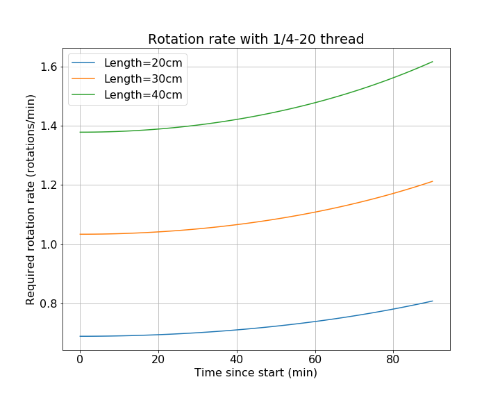
Note: You can check out the Python code used to do these calculations here.
As you can see, the rate changes with time! This is called “the tangent error” and it’s caused by the fact that the acorn nut is sliding along the hypotenuse as the “barn door” opens (see schematic above). There are a bunch of ways people have dealt with it. One is to use a curved screw. Another is to put a specially-shaped cam where the acorn nut contacts the top board. But for this project, I’m simply going to speed up the motor as time goes on if I do a very long exposure. Not having a proper shop, I prefer to use simple physical construction and deal with it in code. If you’re doing 5-10 minute exposures, this issue won’t get to you. Note also that if you have a constant 1 RPM motor, a 29cm L is about right for you.
Putting it together

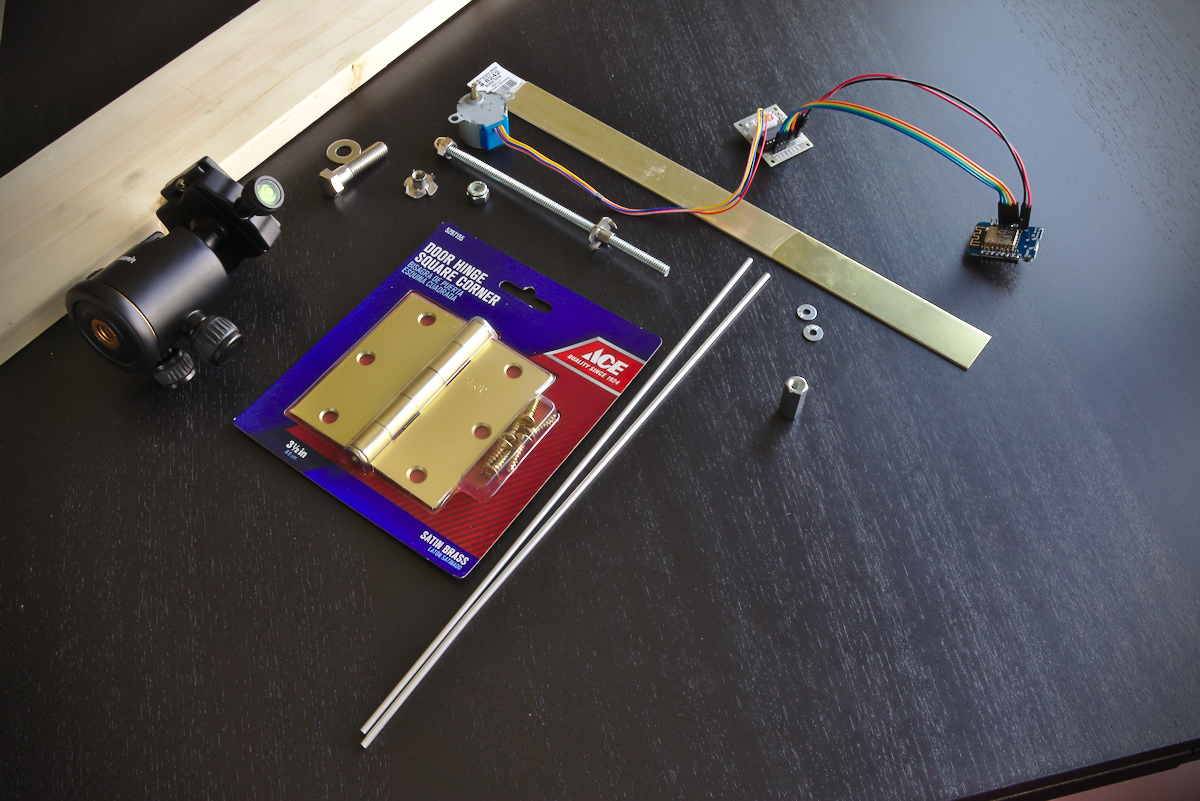
I bought some stuff at the local ACE hardware store to put this together. They had pretty much everything I needed in the hardware department.
My steps:
- Cut boards to size. I chose my total board length as a few inches longer than the 29cm I wanted between my hinge and the shaft. Note that you want to give the top board enough space to open and still contact the shaft, so give it at least 2-3 inches, and longer if you want even longer exposures.
- Attach hinge
- Attach slide plate if you have one (not sure if needed)
- Measure out L from hinge pin and drill hole in bottom board
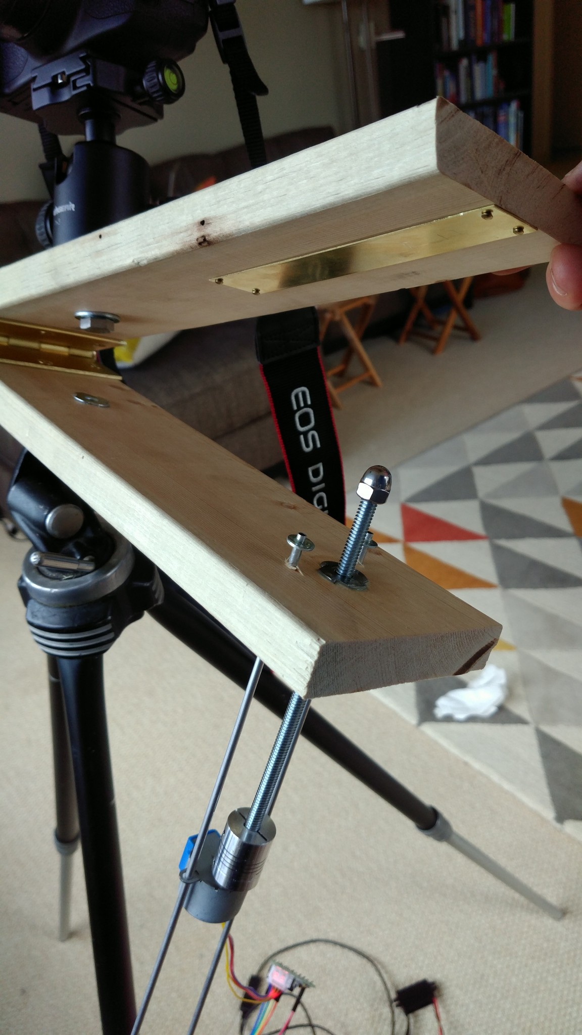
- Apply epoxy to tee-nut for drive shaft and hammer it in place
- Epoxy small washers to the top of rails
- Stick motor shaft in drive hole and mark location of rails
- Drill 1/8″ holes for 1/8″ rails on bottom board and slide them in
- Drill hole for ball mount on top board
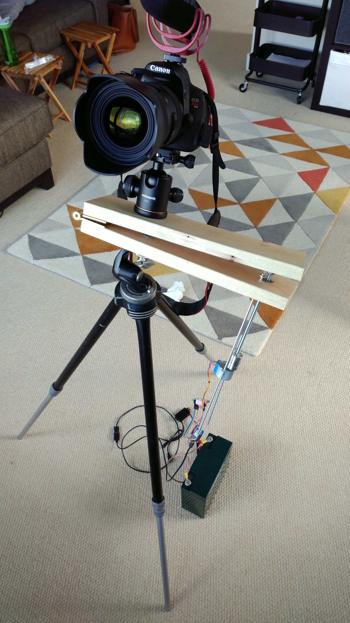
- Mount camera and have a friend help balance it to try to figure out where the center of gravity is on the bottom board. Choose a spot and drill and install 2nd tee-nut for bottom tripod mount. I ended up moving mine from the bottom to the top (so the tripod screw pulls it into the wood, not out) and getting a really long tee-nut for better stability. Then I can really crank down on the tripod screw so the thing stays steady.
- Drill out 1/4″ hole in one side of 5mm coupling nut to attach drive shaft to motor
- Screw threaded rod into main hole, install acorn nut on top
- Put motor on tails and fire it up!
Loud video warning:
Programming the Stepper Motor/MCU
Before I started this project, I happened to have a bag full of stepper motors (like these) and their controllers, and also a bag full of ESP8266 microcontrollers (like these). These are both extremely cheap (like $5 each) items and so I figured they’d be fun to apply for this. ESP8266’s even have Wifi if you want to get super fancy but I didn’t use that here.
Using instructions from here, I got my ESP8266 all hooked up and ready to program using the Arduino IDE. Here’s a good intro to spinning these kinds of motors with code.
Calibration of the ESP8266 delay
First thing I wanted to do was just double check that the timing would be precise enough for what I need (mostly I just wanted to fire up the scope). I got the motor turning with a 5 ms delay, double-stepping and took this measurement from one of the 4 pins:
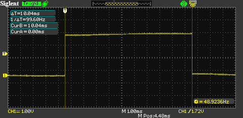
Pretty close to that 10 ms we’d expect. Looks good to me. Here’s the code:
#define NUM_PINS 4
#define NUM_STEPS 8

int allPins[NUM_PINS] = {D1, D2, D3, D4};

// from manufacturers datasheet
int STEPPER_SEQUENCE[NUM_STEPS][NUM_PINS] = {{1,0,0,1},
                                             {1,0,0,0},
                                             {1,1,0,0},
                                             {0,1,0,0},
                                             {0,1,1,0},
                                             {0,0,1,0},
                                             {0,0,1,1},
                                             {0,0,0,1}};
int stepNum = 0;

void setup() {
  Serial.begin(115200);
  setup_gpio();
}

void setup_gpio() {
  for (int i=0;i<NUM_PINS+1;i++) {
     pinMode(allPins[i], OUTPUT);
  }
  all_pins_off();
}

void all_pins_off() {
  for (int i=0;i<NUM_PINS+1;i++) {
    digitalWrite(allPins[i], HIGH);
  }
}

int *currentStep;
void loop() {

 currentStep = STEPPER_SEQUENCE[stepNum];
  for (int i=0;i<NUM_PINS+1;i++) {
     if (currentStep[i] == 1) {
        digitalWrite(allPins[i], HIGH);
     }
     else {
        digitalWrite(allPins[i], LOW);
     }
  }
  delay(5);
  stepNum +=2;  // double-stepping. Faster and shakier.
  stepNum %= NUM_STEPS;
}
Timers, user input, and the accelerating motor
Now for the real deal, let’s code up what we need to do to correct the tangent error and have other practicalities. I was using barebones code for testing and realized it was a pain to reverse my motor (I had to remove wires and rails and twist it by hand. So I decided to add a button to control reversing and stuff.
The motor starts up when you power it up and does its thing. If you press the button once, it reverses all the way back to exactly the starting point (it remembers!), then it stops. If you press the button again, it starts back up.
The delay call in the code above is fine and all, but when the loop step is more complicated (i.e. computing our changing rate), there’s a chance we will not get the right timing. For these kinds of things, there are timers and interrupts. Basically, you write a callback function and register it to be called whenever a specific timer times out. Check it out: (update: this code is available on github)
#define NUM_PINS 4
#define NUM_STEPS 8
#define RADS_PER_SEC 7.292115e-05
#define LENGTH_CM 29.113 // fill in with precise measured value
#define THETA0 0.0241218 // fill in with angle at fully closed position (radians)
#define ROTATIONS_PER_CM 7.8740157  // 1/4-20 thread
#define DOUBLESTEPS_PER_ROTATION 2048.0
#define CYCLES_PER_SECOND 80000000

//modes
#define NORMAL 0
#define REWINDING 1
#define STOPPED 2


int allPins[NUM_PINS] = {D1, D2, D3, D4};
int MODE_PIN = D7;

// from manufacturers datasheet
int STEPPER_SEQUENCE[NUM_STEPS][NUM_PINS] = {{1,0,0,1},
                                             {1,0,0,0},
                                             {1,1,0,0},
                                             {0,1,0,0},
                                             {0,1,1,0},
                                             {0,0,1,0},
                                             {0,0,1,1},
                                             {0,0,0,1}};

int step_delta;
int step_num = 0;
double total_seconds = 0.0;
long totalsteps = 0;
double step_interval_s=0.001;
int *current_step;
volatile unsigned long next; // next time to trigger callback
volatile unsigned long now; // volatile keyword required when things change in callbacks
volatile unsigned long last_toggle; // for debounce
volatile short current_mode=NORMAL;
bool autostop=true;  // hack for allowing manual rewind at boot

float ypt(float ts) {
   // bolt insertion rate in cm/s: y'(t)
   // Note, if you run this for ~359 minutes, it goes to infinity!!
   return LENGTH_CM * RADS_PER_SEC/pow(cos(THETA0 + RADS_PER_SEC * ts),2);
}

void inline step_motor(void) {
  /*  This is the callback function that gets called when the timer
   *  expires. It moves the motor, updates lists, recomputes
   *  the step interval based on the current tangent error,
   *  and sets a new timer.
   */
  switch(current_mode) {
    case NORMAL:
      step_interval_s = 1.0/(ROTATIONS_PER_CM * ypt(total_seconds)* 2 * DOUBLESTEPS_PER_ROTATION);
      step_delta = 1;  // single steps while filming for smoothest operation and highest torque
      step_num %= NUM_STEPS;
      break;
    case REWINDING:
      // fast rewind
      step_interval_s = 0.0025;  // can often get 2ms but gets stuck sometimes.
      step_delta = -2;  // double steps going backwards for speed.
      if (step_num<0) {
        step_num+=NUM_STEPS;  // modulus works here in Python it goes negative in C.
      }
      break;
    case STOPPED:
      step_interval_s = 0.2;  // wait a bit to conserve power.
      break;
  }

  if (current_mode!=STOPPED) {
    total_seconds += step_interval_s; // required for tangent error
    current_step = STEPPER_SEQUENCE[step_num];
    do_step(current_step);
    step_num += step_delta;  // double-steppin'
    totalsteps += step_delta;
  }

  // Serial.println(totalsteps);
  // Before setting the next timer, subtract out however many
  // clock cycles were burned doing all the work above.
  now = ESP.getCycleCount();
  next = now + step_interval_s * CYCLES_PER_SECOND - (now-next); // will auto-rollover.
  timer0_write(next);  // see you next time!
}

void do_step(int *current_step) {
   /* apply a single step of the stepper motor on its pins. */
   for (int i=0;i<NUM_PINS+1;i++) {
     if (current_step[i] == 1) {
        digitalWrite(allPins[i], HIGH);
     }
     else {
        digitalWrite(allPins[i], LOW);
     }
   }
}

void setup() {
  Serial.begin(115200);
  setup_gpio();
  setup_timer();


  // Convenient Feature: Hold button down during boot to do a manual rewind.
  // Press button again to set new zero point.
  int buttonUp = digitalRead(MODE_PIN);
  if(not buttonUp) {
    Serial.println("Manual REWIND!");
    autostop=false;
    current_mode=REWINDING;
  }
}

void setup_timer() {
  noInterrupts();
  timer0_isr_init();
  timer0_attachInterrupt(step_motor);  // call this function when timer expires
  next=ESP.getCycleCount()+1000;
  timer0_write(next);  // do first call in 1000 clock cycles.
  interrupts();
}

void setup_gpio() {

  for (int i=0;i<NUM_PINS+1;i++) {
     pinMode(allPins[i], OUTPUT);
  }
  all_pins_off();

  // Setup toggle button for some user input.
  pinMode(MODE_PIN, INPUT_PULLUP);
  attachInterrupt(digitalPinToInterrupt(MODE_PIN), toggle_mode, FALLING);
}

void all_pins_off() {
  for (int i=0;i<NUM_PINS+1;i++) {
    digitalWrite(allPins[i], LOW);
  }
}

void toggle_mode() {
  /*  We have several modes that we can toggle between with a button,
   *  NORMAL, REWIND, and STOPPED.
   */
  if(ESP.getCycleCount() - last_toggle < 0.2*CYCLES_PER_SECOND) //debounce
  {
    return;
  }
  if (current_mode == REWINDING){
    Serial.println("STOPPING");
    current_mode = STOPPED;
    all_pins_off();
    if (not autostop) {
      // Reset things after a manual rewind.
      step_num = 0;
      total_seconds = 0.0;
      totalsteps=0;
      autostop=true;
    }
  }
  else if (current_mode == NORMAL) {
    Serial.println("Rewinding.");
    current_mode = REWINDING;
  }
  else {
    Serial.println("Restarting.");
    current_mode = NORMAL;
  }
  last_toggle = ESP.getCycleCount();
}


void loop() {

  if(current_mode == REWINDING) {
      // we've reached the starting point. stop rewinding.
      if(totalsteps < 1 and autostop==true){
        Serial.println("Ending the rewind and stopping.");
        current_mode=STOPPED;
        all_pins_off();
      }
  }
  else {
    // no-op. just wait for interrupts.
    yield();
  }
}
(That bit about setting the timer at the end of the callback took some trial-and-error… it kept crashing around 4.2 billion clock cycles. Turns out that’s the max unsigned long int value. Neat. )
Portable use and Power Consumption
Stars are better when it’s darker, and that often requires remote operation. This thing runs off a USB port so if you have one of those external batteries, that should work. I tried a few options here, including a big deep-cycle battery that I use for ham radio for the really long hauls.
Through a 12V-to-5V converter, I measured 0.189 Amps, yielding 2.27 Watts. So my huge 20Ah battery could run it for 4 full days. More practically, 3 of those common lightweight Li-ion 18650s chained together would run it for over 2 days (wow). So that’s nice.
Polar alignment
It’s important to get everything aligned so it works right. You have to make sure:
- Your finderscope is aligned with the hinge axis (swing it and make sure a faraway thing like a star stays in the middle).
- Your finderscope is pointed at the celestial pole (close to Polaris, but not right on it)
I set a straw on my hinge and aimed it at a tower crane in the distance. Then I pointed the camera at the same crane and rotated it. With some adjustment it didn’t rotate too much, so at that point I could point the camera at Polaris, lock in the tripod, and be off.
For the longer term, I ordered one of those red-dot things from the internets because my dad got one years ago for his telescope and it was great. Once get it aligned I can just point-and-go.
UPDATE: I got it (see picture in angular calibration section below) and it is perfect.
First attempts at using
I tried it out with the straw-on-the-hinge alignment and got it sort-of aligned, to the point that I couldn’t wait to turn it on and try it. This was from downtown downtown Seattle so the light pollution was pretty intense. Fortunately I shot in RAW and could get some stars out of it.
Test number 1: It works!
Then I just pointed it around and did what I could.


Not bad. It wasn’t perfectly aligned so I’ll do more serious tests once I get that done and head to some actual dark sky.
UPDATE 2017 Eclipse in Oregon
I used it on the eclipse and it worked great. It was nice to have the camera clicking away with exposure bracketing so I could watch the eclipse myself. I’m really happy with the result.

UPDATE 2020 Use with Neowise
I used it on C/2020 NEOWISE F3 comet and it worked amazingly well.

UPDATE 2024: Eclipse in Missouri
It worked again in Missouri!

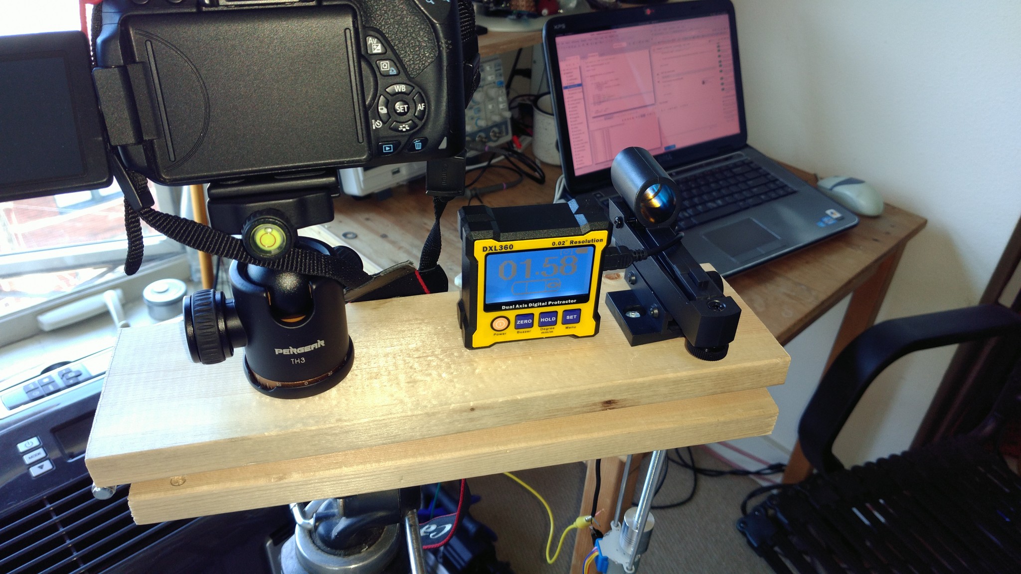
Precise Angular Velocity Calibration
Just to check my math a bit more, I got a digital level and figured out how to get it to dump data to my PC. Then I let it run with my tracker for a while and did some least-squares fitting to see how it was working.
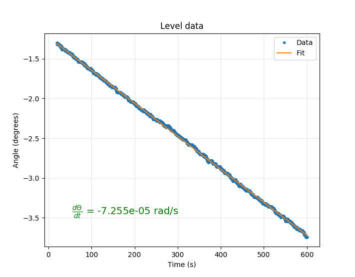
So I measured a nice and constant 7.255e-5 radians/second over 10 minutes. That’s within 0.5% of the right answer. I can now adjust my target in software to speed it up by 0.5% and get it really accurate! The calibration software is also available on github.
Future work
Get a telescope. Learn how to stack photos.
Some references
- D1 Wemos Pinout for esp8266
- Info on timers on the ESP8266
- Some info on ESP8266 software timers that I didn’t use
- Info on controlling these stepper motors from code
- Info on celestial alignment of trackers
- All the people on /r/astrophotography who made things like this before
Neat write up and project, thank you. Be fun to build. First look, seems you have a nice solution for attaching a stepper motor to the threaded rod. Can you let us know how/ part number please
That’s just a 5mm coupler. I actually had to drill out one end of it a bit to get it hooked up to the threaded rod. Not too elegant.
https://www.amazon.com/gp/aw/d/B010MZ8SQU/ref=mp_s_a_1_1?ie=UTF8&qid=1499008818&sr=8-1&pi=SL75_QL70
The other way I have seen this done is for the rod to be affixed to the top plate and bent around an arc with R = “distance to hinge” and have the nut driven by a gear or rubber timing belt.
Both methods are valid, with yours seeming to be easier to software troubleshoot for minor errors. The arced rod version lets you find tune with a potentiometer or adjustable PWM, on the other hand. Makes for a simpler electronic build.
I saw those too and that should work great. You can also attach a shaped cam to the top plate to do the correction. I just wanted to throw a twist into the mix with this software-heavy option.
Could you give a list of the parts. I know you show the receipt, but a list of hardware would be great.
Please thanks,
Ken
Getting an error
D1 is not declared in this scope
Ah. Ok so the constants D1, D2, etc. are defined in mine because I have my board set as the “Wemos D1 R2 & mini” in the Board Manager, which was the particular ESP8266 package I purchased. They just point to certain pin numbers as mapped here: https://github.com/esp8266/Arduino/blob/master/variants/d1_mini/pins_arduino.h
D1 is actually pin 5, etc. Your board may vary. Just point to the pin number you’re plugged into as integers if you have some other board.
Thanks so much for the quick reply. Actually it was the serial driver… eek!
On another note, how long is the 1/4 20 bolt?
Nice! My bolt is 6 inches long.
Wow Really nice project
How many steps per revolution on your stepper motor?
64 steps for the motor to rotate and it’s geared through a 1/64 reduction gear so it takes 4096 single steps to go all the way around on mine. I sometimes use double-steps to make it faster, it’s still pretty strong.
Nice project. Do you have a quick way to reset? Run the stepper in reverse?
I’m sorry, just found rewind part. Impressive. thanks for sharing!
Great project! Thanks for the write-up.
Curious, does that little stepper have any problems with the weight of your DSLR?
Any idea how much weight it will handle before having to move up to a larger stepper? With my DSLR, 400mm lens, and ball head I am looking at about 9 lbs.
Much Thanks…
Thanks! This stepper handles it very nicely with my big heavy Sigma 18-35mm Art 1.8 and could handle much more. I can hardly stop the stepper with my fingers gripping really hard and all it has to do here is spin the screw so it gets mechanical advantage on top of that. You’ll be fine with your equipment.
Hi, thanks for sharing your project, but i have a question : can you give us the reference of the nut you used to fix the barn door to the tripod? (and the reference of the bolt you used to fix the ball to the barn door)
Sure: I used threaded T-nuts (just google that for pics) on both of those with a bolt that fit. You just hammer them in. To be honest, they’re not as stable as I’d like and for a second one I’d probably recommend using something like this with epoxy: https://www.woodmagazine.com/materials-guide/fasteners/tips-on-using-threaded-inserts
Hey, this is an awesome build, definitely a lot of thought put into it! I made my own a while back and started selling kits because people liked it so much. Just thought I’d link it here if people wanted to check it out as another option. 🙂 Clear skies everyone!!
http://nyxtech.us
(apologies if this is a duplicate comment, I think I encountered an error while posting a minute ago)
Thanks! Beautiful build and kit, thanks for pointing us to it.
Thanks heaps for this; I have now made it as a project with my girls however I am finding that the door is opening too quickly and I have tried working out how to slow it; could you please point me in the right direction.
Hi Dave, glad to hear you and your girls built one. All the “settings” for speed are in the first few lines with those defines. You may have to adjust them to fit your dimensions, your threaded rod, and your motor. If you’re using a metric pitch threaded rod instead of the imperial one I’m using, the ROTATIONS_PER_CM will have to be different from what I used. For instance, if you’re using a 10 mm diameter rod with fine pitch, you’d have 1.25mm pitch, or 0.0125 cm of insertion per rotation, or 8 rotations per cm. So you’d change my number 7.87 to 8 below.
Can you tell how much too fast your is spinning? If you measure how much the threaded rod inserts over 5 minutes or so that’d be enough for me to make some more guesses.
#define LENGTH_CM 29.113 // fill in with precise measured value

#define THETA0 0.0241218 // fill in with angle at fully closed position (radians)

#define ROTATIONS_PER_CM 7.8740157  // 1/4-20 thread

#define DOUBLESTEPS_PER_ROTATION 2048.0

#define CYCLES_PER_SECOND 80000000
Cannot wait to try this. Deep skystacker for Windows is free and works great.
Thank you!
Hi Nick,
Been working on this project, and I’m almost finished, but I found out that the 1/4″ thread on my tripod is also sticking out only 1/4″ above the tripod head. How did you work around this? I can’t tell from the images.
I did have a similar problem that I should have mentioned since maybe this is common. I may have gotten a little lucky in that the main platform of my tripod is detachable and I was able to pop it off and get a bit more grab. Without that, you may have to look for some kind of extension coupler for those threads. Sorry, but good luck!
I was in (some sort of) luck as well. Since I’m in Europe and everything is metric, I drilled out the hole where the tripod thread was coming out of to 8mm, and used an 8mm t-nut and bolt to secure it in place, without widening the gap so much that the original tripod thread can’t be used anymore! So now it’s a multifunctional tripod!
Thanks for this post. I have made two versions, the second one vastly more reliable than the first one. It’s been really fun to build.
A lots of mathematics (your hobby too?) and therefore it’s far from simple; it’s very complicated and therefore completely worthless for me; electronics also very difficult
That’s fair. I guess the electronics/software stuff isn’t simple. It’s just simple on the physical side.
It may be silly question but i am not able to get the reason for programming the stepper motor. can you please explain? Thanks in advance.
The rate of stepping has to change as the bolt extends in order to keep the rotational velocity constant. It’s just a triangle geometry thing.
well done! is it possible for this code to work on arduino nano or similar? maybe someone has already done it. Unfortunately, I can’t do it 🙁
Thanks! It should be totally possible to do that. In fact, the code is written within the Arduino IDE. There are probably a few differences with the timers and whatnot to get it just right, so it would take a little expertise on that front to figure it out. Maybe it’d be a good excuse for me to get a nano finally and see if it could be ported.
Thank you, this is good news, I will keep my fingers crossed for you. Of course, I will also try myself although I am just beginning.
Hi, I’m in the process of ordering all the parts for my barn door tracker, however the tripod-tracker tee nut seem to be a big issue. I can’t seem to find any 1/4 20TPI UNC tee nuts anywhere. In the UK, all I can find is M6/M8/M10 tee nuts, no TPI values at all.
If you could shed some light on which size would work, that would be great.
Cheers
You can definitely use a metric thread for the tee but. Just be sure to get a compatible bolt. You’ll have to adjust the dimensions too. I believe a M10 has 10 threads per cm.
Hi, I made a simple version with a fixed arm length (29cm) on arduino – it works. Now i bought the esp8266 module in the form of NodeMcu v3 for the short arm version and i am trying to upload your code. Unfortunately, after uploading the project, the module resets every 6-7 seconds displaying the following data :
ets Jan 8 2013,rst cause:4, boot mode:(3,6)
wdt reset
load 0x4010f000, len 1392, room 16
tail 0
chksum 0xd0
csum 0xd0
v3d128e5c
~ld
what am I doing wrong?
Hi,
First of all, an amazing project and well done to you. I have a question: Is the size of the wooden boards important? What dimensions did you use?
Hi Patel
I had the same error, you need to downgrade the ESP library in the Arduino IDE to 2.4.2.
Could anyone advise me how to attach the switch please? I’ve got everything else working but cannot see how the switch connects?
Thanks for finding the fix for that error. I should see what the problem is and update the code.
The switch that controls the rewinds and stuff? Oh yeah sorry I did not show that. It’s just a connection from the digital input GPIO pin to ground.
Thanks for the quick reply, sorted now. Works beautifully.
There’s nothing wrong with the code, from what I’ve read there are issues with later versions of the ESP manager with regard to interrupts, they can be solved by changing the code but it’s much easier to downgrade the board manager. (I’m no expert, this is info from googling).
Hi Nick,
I’m building a tracker based with your timing code with a couple of changes to allow it to be started and stopped from an external controller and also an auto-shutdown based on elapsed times; in that I’ve found that the newer libraries for the ESP8266 with Arduino cause the script to throw a wdt timer error after a few seconds due to the interrupt for the toggle_mode not being loaded in to the RAM.
To solve that, I’ve found that adding these to the top of the code stops it from occurring; that’s with the current board package (2.7.4) with IDE 1.8.13.
#ifndef ICACHE_RAM_ATTR
#define ICACHE_RAM_ATTR
#endif
void ICACHE_RAM_ATTR toggle_mode();
And for adding any further interrupts doing the same with void ICACHE_RAM_ATTR interruptName();, though it doesn’t occur with the step_motor() callback.
Also the other thing I’m attempting to do with it, is to calculate the Theta0 at run time as it’d make it easier to swap the system between trackers if need be just with the changing the script variables on the cell phone and uploading from there instead of needing to take a computer to do that with. That has left me with a bit of confusion, as in the calculations in the Python for the distance for calculating theta0_rad, there’s a value of 4.70. Would this be the distance between hinge centre and the point of measurement for the height_at_hinge?
Oooh I’m excited to hear about your build. Thanks for the code updates! I haven’t re-built the code for a while but will apply your changes and do so and then update the code posted.
Your assessment of the 4.7 is correct. I’m not sure exactly why I chose 4.7cm away from the hinge but the height at the hinge was hard to measure so I just measured the height 4.7cm in from the hinge. I should update that confusing/wrong variable name! Thanks also for pointing this confusion out.
Thanks for the clarification Nick, now I know what the variable is I can put that in to the sketch.
When I’ve tested the modifications that I’ve done, though it won’t be outdoors at the moment given the present situation where I live, I’ll pass a link to download the sketch with modifications so it’s easier to see them within context.
Hi Nick,
Here’s a link to the sketch with some of the ideas I’ve had with it, https://drive.google.com/file/d/11U4HdbTtPTz11lKPXblbewHRqXDPL82W/view?usp=sharing
I’ve tried to keep it as much as you wrote it where possible, and have commented up the areas that I’ve changed with it; if there are any parts that I’ve done here that you find useful and want to implement for distribution on the sketch above, I’m happy for that to happen.
Hi Nick,
as a mathematician/computer scientist, I was delighted to stumble upon you approach: easy setup and complex code.
In the end, are you happy with your tracker? Would you recommend it? Do you know how it compares with trackers that use curved screw? Do you see how your code could be made more precise?
Thanks,
Charlie
Hi Charlie,
Thanks for the note. I am happy with the tracker for sure. It may note be professional-grade, but it has served my purposes well, and was fun to make. I have not used any other trackers to be honest so I’m not sure how it compares. I also am not aware of any way to make my code more precise, but I have no doubt that such possibilities exist 😉
After reviewing the various barn door type mounts here: http://davetrott.com/inventions/double-arm-barn-door-drive/
and the analysis of the “type 4 double arm barn door” mount – a more complicated design that mechanically compensates for the tangent error here: https://www.cloudynights.com/topic/114159-analysis-of-type-4-barn-door-mount/
It is clear the benefit of the “type 4” design is sensitive to construction accuracy. I am concluding that perhaps a more accurate tracking in a DIY project can be achieved with the simpler barn door design like yours driven by a compensating computer drive, then fine tuned after construction.
After fine tuning yours with software, were you able to reduce error below 0.5%? Where did error rate finally end up? How long can you track without star trails (and with what lens, etc.)?
Hi. Thanks for sharing. A question: the theta angle increases with time. So as the threaded rod is rotated dL/dt shouldn’t it be reduced to compensate for the theta increase? Or Does changing the contact point between the nut and the top plank compensate for this effect? Because the hypotenuse gets bigger with time…
Yeah L is always constant in my build because the nut is sliding under the top plank. The hypotenuse is indeed getting longer as it rotates.
Hello Nick!
I stumbled upon this page in my search to learn more about building a star tracker and I have to say this has been incredibly informative. One thing that I’m still a little confused about is the “tangent error”. I’m just a bit confused on the relationship between the acorn nut sliding and the hypotenuse, as well as how that is creating an increasing rate of change with regards to theta of t when what we really want is a constant rate change. Is the “tangent error” seen in all barndoor trackers that involve two plates moving apart from one another via a threaded rod/bolt? My other question is with regards to the bolt insertion vs time start graph. Does bolt insertion refer to the length of the threaded rod “in the triangle” with respect to time? Thank you!
Hello Nick!
It’s a good article for my appetite as I like doing stuff myself. I have started using film cameras recently to take pictures again as I do like the hands-on nature of analogue photography. A nifty star tracker like this one would be very handy to shoot the milky way using film. Thank you for the nice article!