I’ve always dreamed of having a “smart-home.” There’s just something cool about being able to flip switches and read sensors and have a program turn a light on when you open the door, but only if it’s dark. This post is about home automation.
My wife got me an early birthday present: Philips HUE Color-Changing LED lights! They’re incredible. Look:
Right now I’m controlling them with my tablet, which is fine for changing colors and setting light alarms. I can even control them from afar thanks to my VPN. I will soon hook them up to my nascent Raspberry Pi powered home automation system (using the open-source Home Assistant program) that will allow me to trigger them based on various events like motion, doors opening, weather changing, or whatever. The future is here!
Each bulb uses 9 Watts but makes the same amount of light as a 60W conventional bulb, so they’re very eco-friendly. Furthermore, since they’re LEDs, they should last for 15 years of normal use! They communicate with a little hub that uses the ZigBee protocol (like Bluetooth but lower power and lower speed, good for home automation stuff).
Downside: They’re pretty pricey. I expect their coolness to drive demand enough to bring supply up. Expect these bulbs for $10 in the next few years.
Sending and receiving text with Morse code light pulses across the room (or to your neighbor) is a fun and cheap project you can do on a Raspberry Pi or Arduino or any other microcontroller. This post explains how I did it, and how you can do it too.
It’s working!
Hardware
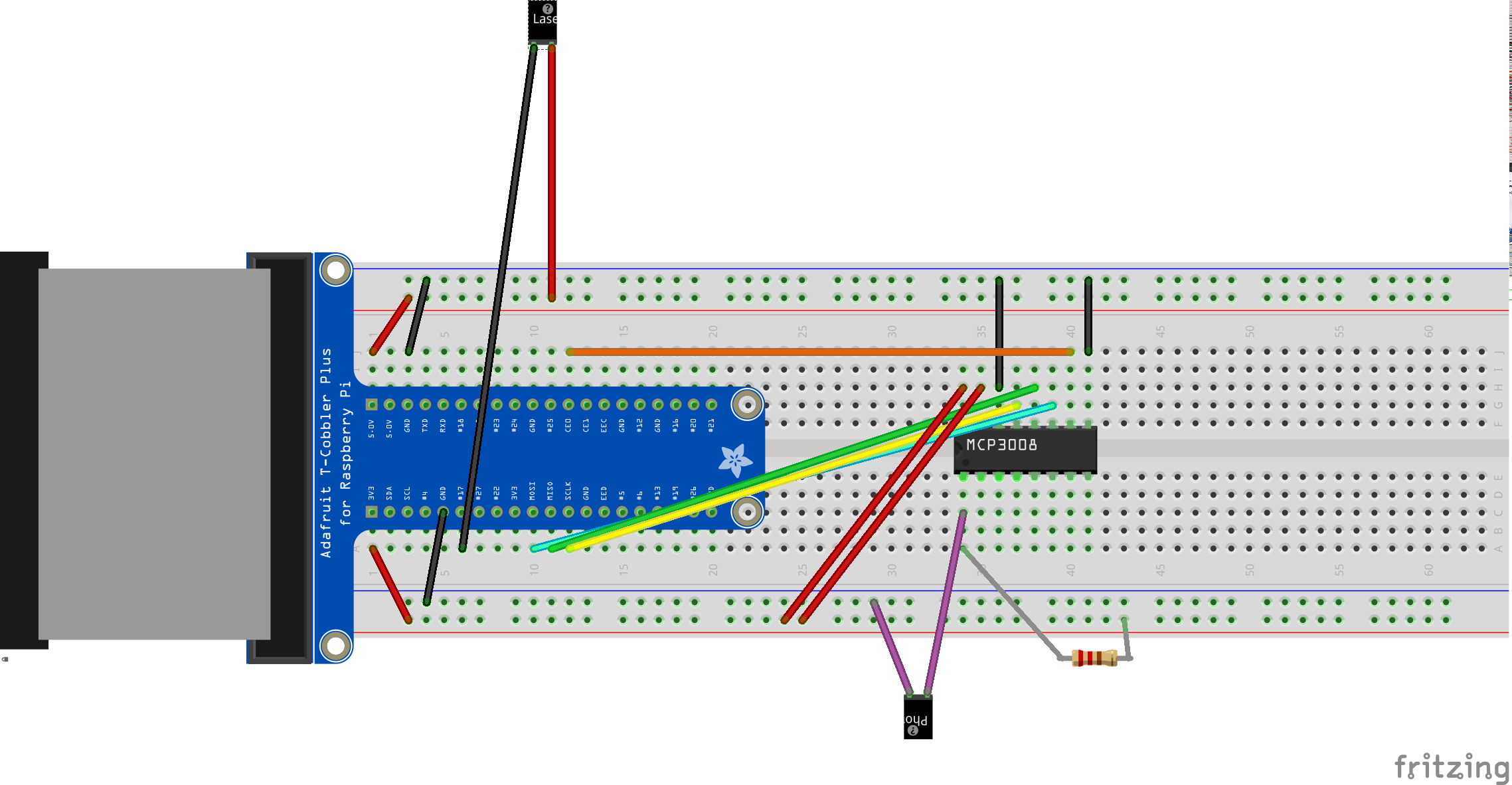
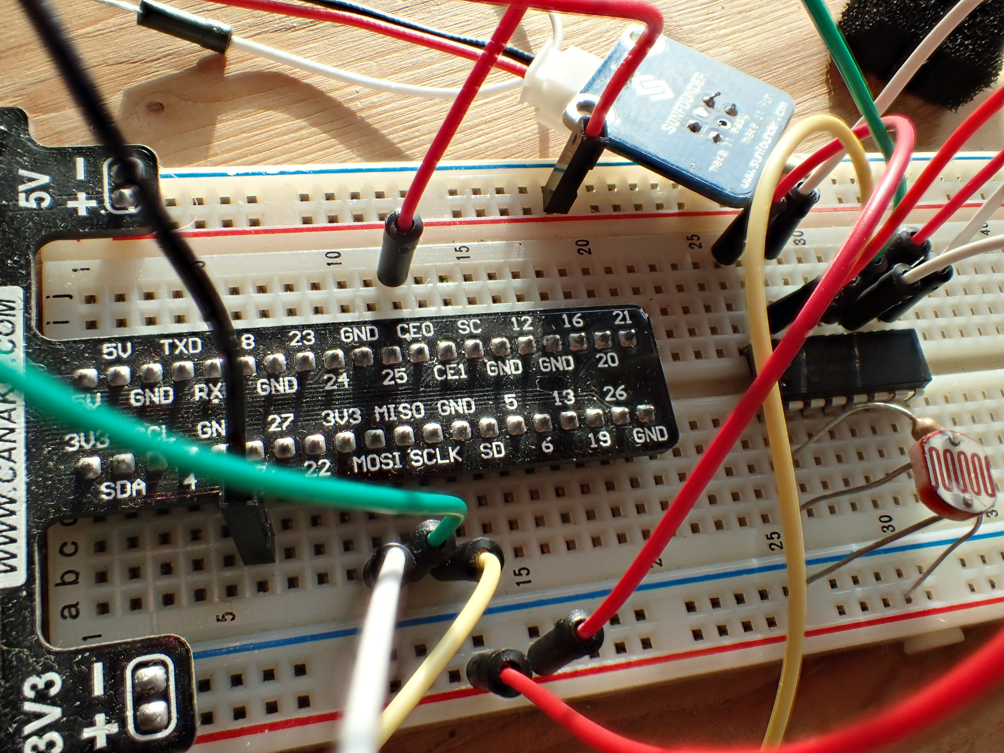
The hardware is simple and cheap. Here’s my parts list:
Raspberry Pi B+ as the controller. This does the sending, receiving, and signal processing.
Photoresistor – Just a little guy that has variable resistance based on how much light is hitting it
A 220 Ohm resistor – to make a voltage divider with the photoresistor for reading the input signal
MCP3008 10-bit Analog-to-Digital Converter (ADC) – Since the RPi doesn’t come with an ADC, this is required for converting analog voltage from the photoresistor into a signal I can process on the RPi.
Laser module – to transmit with laser light. I got one from sunfounder.com for like 3 bucks.
Breadboard, wires
You can learn how to use the ADC at this Adafruit tutorial. I decided to talk to the ADC with the RPi’s hardware SPI interface, which I had already enabled. I wanted to be able to go very fast. (You can alternatively do SPI off of GPIO ports with software, if you prefer.) The laser just hooks directly between a GPIO and +5V. Here’s the layout:
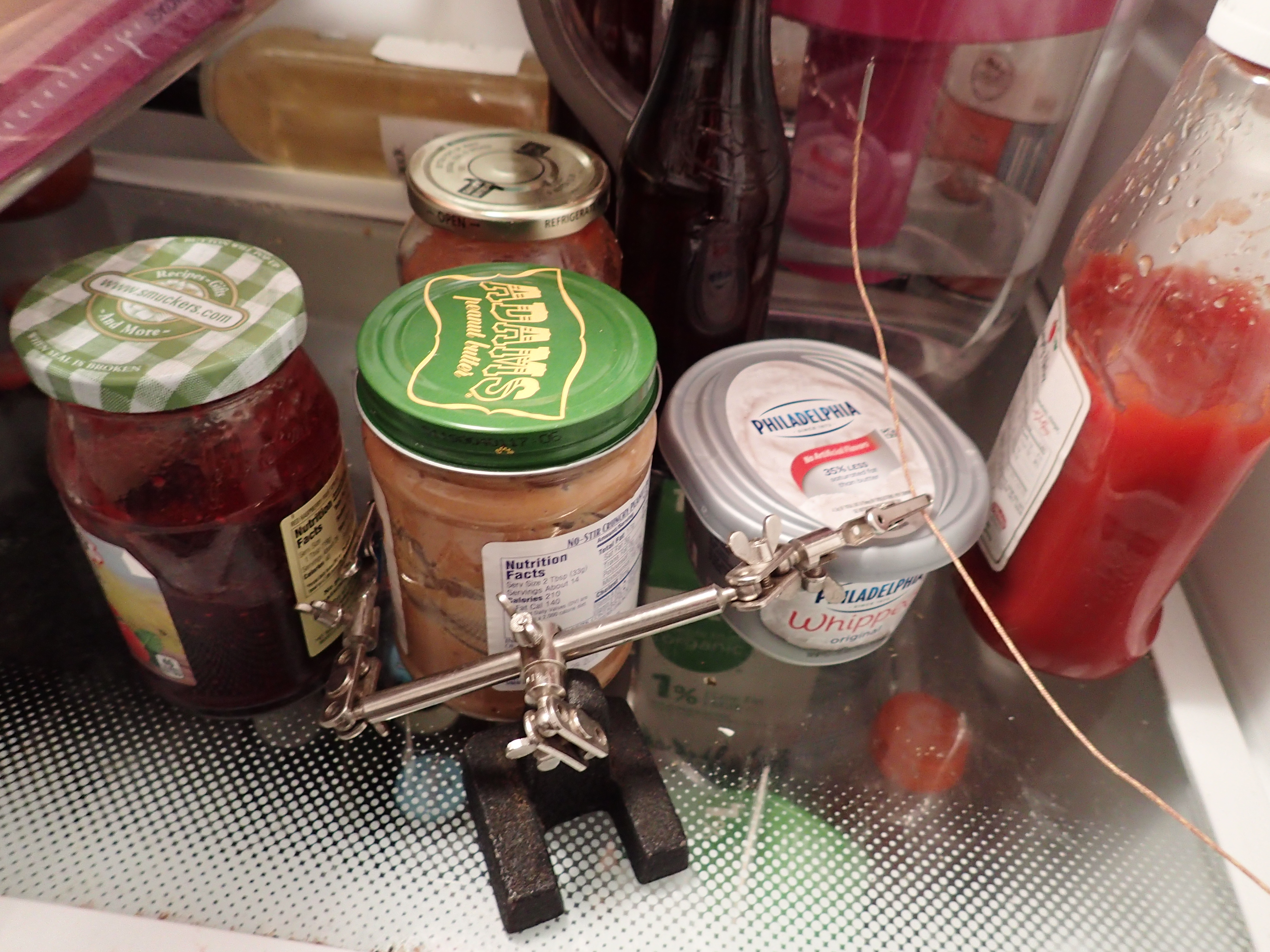
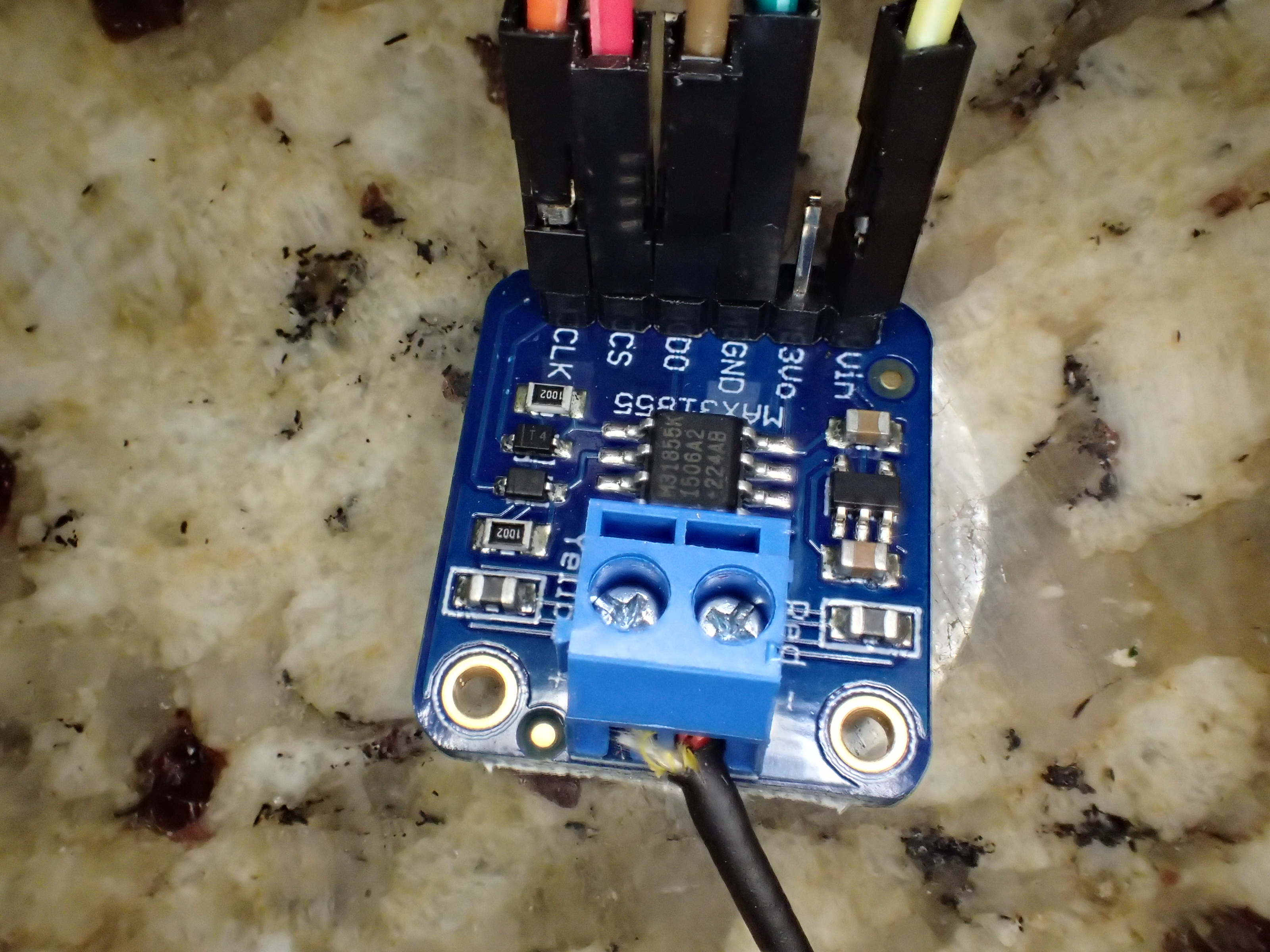
Sensors are fun!I wanted to keep an eye on the temperature of one of my home physics projects and realized I needed a thermocouple and a convenient way to read it. This post is about how I got one and wrote a Python program to send the data from a Raspberry PI over the network to my laptop, which plots the results in real time.
Thermocouple in fridge
I bought a K-type thermocouple for several dollars that ranges from -100°C to 500°C. The Seebeck effect that makes it work only gives microvolts per degree so I needed a good amplifier for it. And since I wanted to read it on a Raspberry PI (which only has digital inputs), I’d need an analog-to-digital converter (ADC). Conveniently, the MAX31855 does amplification and ADC and is like $15, so I got one. Sweet. There’s even a Python library for it that makes it easy to access. Double-sweet.
Alright, this is an oldie, but ah… well… it’s and oldie where I come from. In 2005, I had some healthy spare time and decided to build a flux capacitor. I posted the details on my old webpage. I just rewired a battery pack on it and it’s working fine so I figured it was time to get it back online again. So, here it is. How to build a LED flux capacitor.
The Concept
In the movie Back to the Future, Dr. “Doc” Emmett Brown completed his life goal of making the flux capacitor a reality. Here’s the story:
“I was standing on the edge of the toilet hanging a clock, the porcelain was wet, I slipped, hit my head on the edge of the sink — and when I came to I had a revelation! A vision! A picture in my head! A picture of this! This is what makes time travel possible! The Flux Capacitor.”
-Doc, Back to the Future
The Flux Capacitor
Unfortunately, I didn’t have room for the time circuits or nuclear reactor to generate the 1.21 jigawatts that the flux capacitor needs to travel in time so we’re going to have to go with the next best thing: A 30 LED sequencer!
Since I’m on a late 1800s physics kick, I’ve been staring at my Crookes radiometer a lot.
My Crookes radiometer, or light-mill
You might remember these from the hands-on museum. Today, these are just novelty items, but back in the 1800’s, there were actually scientific instruments that could quantitatively read out the amount of incoming radiation (like visible or infrared light). They were generally read out using a calibrated spinning disk with slots in it. It’s like when you have a fan spinning in a dark room, and you adjust a strobe light until it looks like the fan isn’t spinning. Then, if you know how fast the strobe is blinking, you know how fast the object is spinning. This is called a stroboscope.
Well, I don’t have a stroboscope. But I do have a digital camera and a computer. As it turns out, I can read the Crookes radiometer using that!
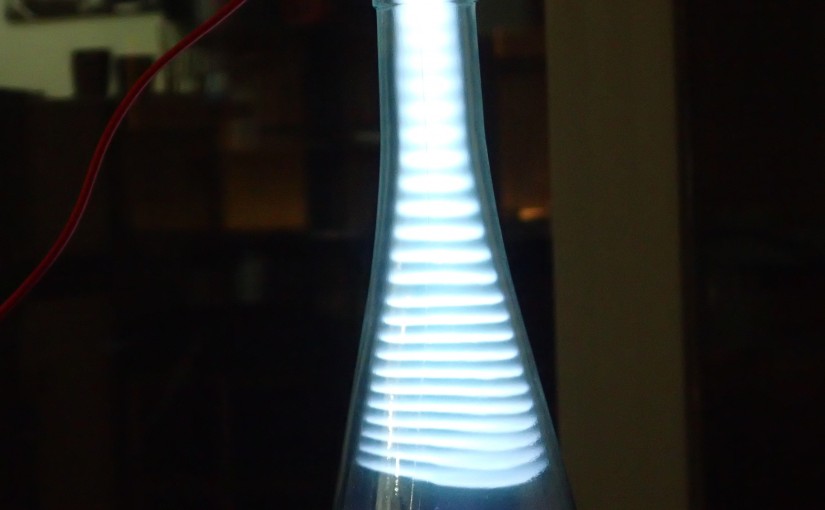
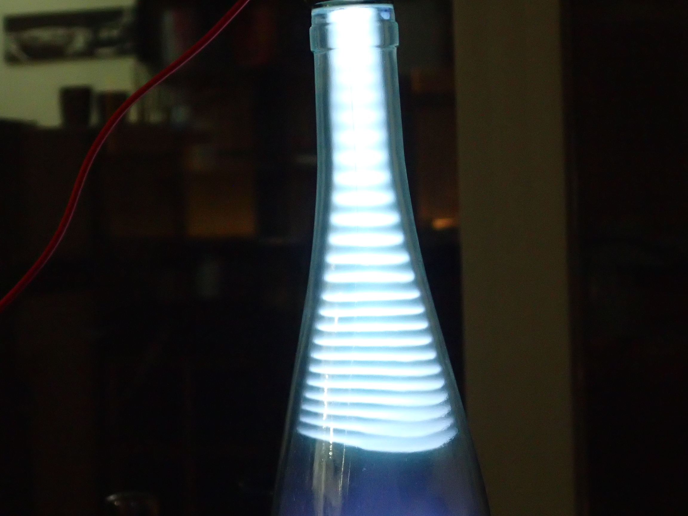
Or, why I built a cathode ray tube in a wine bottle.
I was leisurely reading Linus Pauling’s textbook, General Chemistry, the other day, and I found the history he threw in there with the science to be thrilling. For instance, I learned quickly that the Greek word for amber, elekton, forms the base of our word electricity, so named by William Gilbert in the late 1500s because the ancient Greeks knew that rubbing amber with wool would attract feathers and stuff. As a nuclear engineer whose job it is to make electricity, this was a fun revelation. Pauling continues to mix physical realities with the experiments used to prove them, and doing so, he quickly arrives at the cathode ray tube. After reading and thinking about it, I had another revelation. It turns out, I realized, that some large fraction of modernity, from the world order to modern health, the environment, politics, and the media passed through a cathode ray tube. Here’s how.
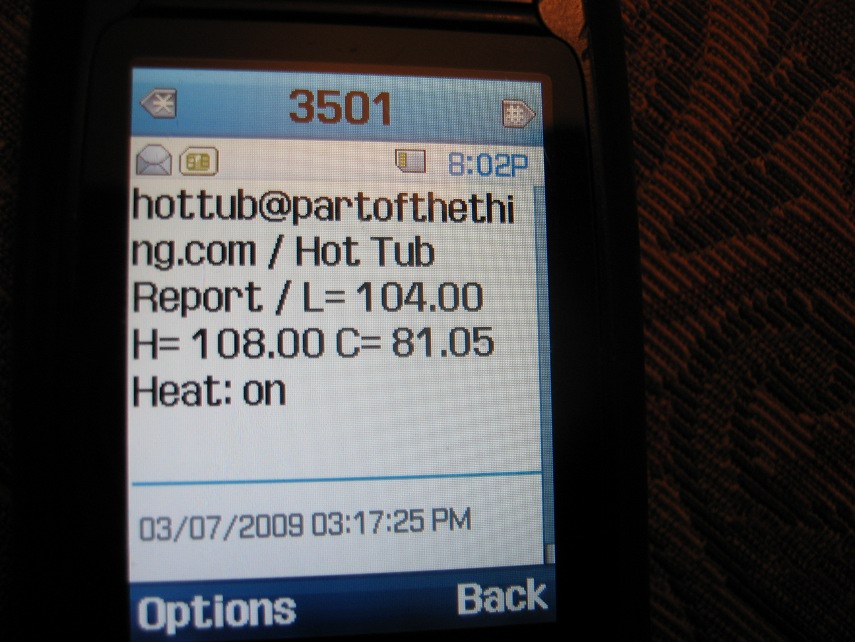
So, I have to tell you about the hot tub project. It’s been going on for a few weeks now and we just basically finished it. I (with some help from Jesse) have set up a microcontroller to control and monitor the hot tub. We have a temperature sensor mounted on the heating element tube and we wired in a relay to control when the heater turn on. Then we wrote code to allow it to interface with email, the internet, and even text messages! For real. Look:
Text message from the hot tub
Haha! Here are some more gems:
and you can control it with this form:
Or you can just control it from the command line:
So here’s what’s going on. Firstly, there’s an arduino connected to a USB port of the computer in the basement. Here’s a pic:
One of the digital pins on the Arduino is connected to a OneWire bus with three temperature sensors hooked up to it with a pull-down resistor connecting the bus to the 5V line. That’s the green wire. The ground is white ground. The three sensors are hooked up (in parasite power mode) to 30 feet of indoor/outdoor CAT-5 wire from Home Depot. I surrounded each temperature sensor with a piece of 3/8″ O.D. copper tubing (which is miraculously already corroding) and pinched them down and sealed them up with Silicone. Here’s a pic of the outdoor sensor.
Anyway, yeah. The last sensor, the one on the tub, is wrapped in lots of insulation from the hardware store to try to keep the outdoor temperature from affecting the hot tub readings.
On another digital pin (the orange wire), we have a relay circuit that we can turn on and off easily. In the hot tub, it connects the wire that connects the coil of the main heater relay. So it’s a relay for a relay, effectively. We just set the temperature dial very high and use the Arduino to cut it off when we want. We got the circuit from here. Here’s a copy of that:
Nice. I used a relay that can handle up to 30A, 240V, with a 12V coil. I got the 12V by splicing off of the hard drive power cable inside the computer (blue wire, with white blue as ground. That’s the same ground, but we didn’t want to tap into the fragile cat5 wire again). That’s unfortunate because it requires the computer be on to have the heater on. A better design would not rely on the computer to maintain control of the hot tub.
The rest of it is just software. I’m using the pySerial module to read and write to the USB tty device in 32-bit Ubuntu 8.10 Linux. The code that I compiled on the Arduino chip simply accepts simple characters through the serial port and does as asked. It knows how to turn heater on, off, read temperatures, and tell whether or not the heater is on. I’ll build some safety logic in soon. Right now, all the control logic and communication is done in Python on the computer. I have an Arduino class that abstracts the commands the Arduino knows. Then there’s the hottubController class that checks the sensors and turns the heat on and off accordingly. It calls the communication class, that checks for commands in an IMAP email account, submits temperature information to a MySQL database on my server, and sends command responses via SMTP. The text messaging functionality works simply because you can easily use the text-to-email gateways used by many major phone companies. The MySQL stuff is done with the MySQLdb python module, which is fairly simple.
The web form is a python cgi that makes that simple HTML table and sends the commands in. The plotter is another python script that reads the database and puts the data into an HTML file, which is then parsed by the flot JavaScript plotting routines on the clientside, allowing zooming and dynamic date x-axis labels, which are awesome.
Still to come: predictive hot tub times. Since the heating is very linear, it’s possible to extrapolate the time at which the tub will reach a given temperature. You’ll get a text that says: “the hot tub will be ready at 10:37PM” How cool will that be at the bar?
With all the copper, casings, arduino, sensors, relays, silicone, insulation, and various other tools I bought during this, it’s up to about $100, not including the computer. Not bad!
More Details
In case you’re wondering or debugging the hot tub controller, here are some more details.
The breadboard setup for the hot tub controllerHere's what the arduino wires look like. Nothing special.
Out at the hot tub, you’ll see a silver toggle switch. Under normal operation, this should be in the center position. To shut down special features and go back to plain-old hot tub, put the switch in the up position. This gives control of the hot tub back to its internal thermostat. It also disables the 10 second heater delay relay.