I had a flood in the garage the other day and realized how great of an investment my flood sensor had been, saving me literally weeks of time and thousands of dollars in repairs. As I considered buying more flood sensors to cover more parts of the house, the thought to put a flow meter on the main water inlet to the house popped into my mind. It’s not quite as clear of a signal as a flood sensor, but if I detect flow when everyone is asleep or when on vacation, I can be sure that something is going wrong and have Home Assistant give me an alert.
I didn’t want to cut into my water main and put a in-line flow meter in, so when I saw a reasonably priced clamp-on ultrasonic flow meter called the TUF-2000M, I had to bite.
I also purchased a water main valve actuator to turn off the water automatically but it was not strong enough to actuate my valve so I sadly had to return it.
The kit comes with a lot of wire and a power cord. You have to strip them yourself and hook them up. BTW, the power transformer is totally crap and broke almost immediately in a kind of scary way.
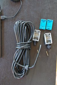
The transducers and wire 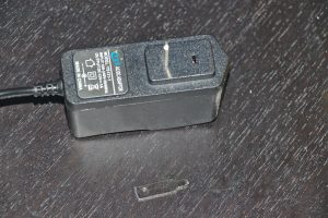
The garbage 12V transformer (luckily I had another 12V one around)

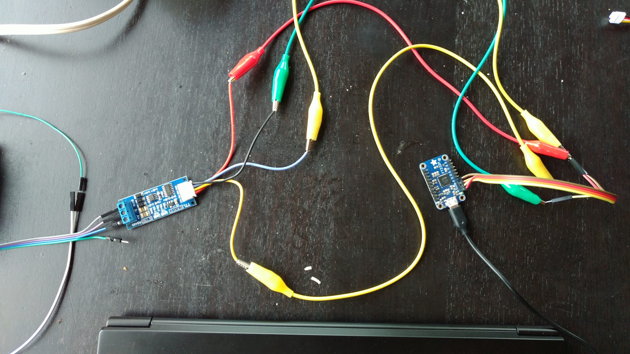
Getting the RS-485 data into a computer
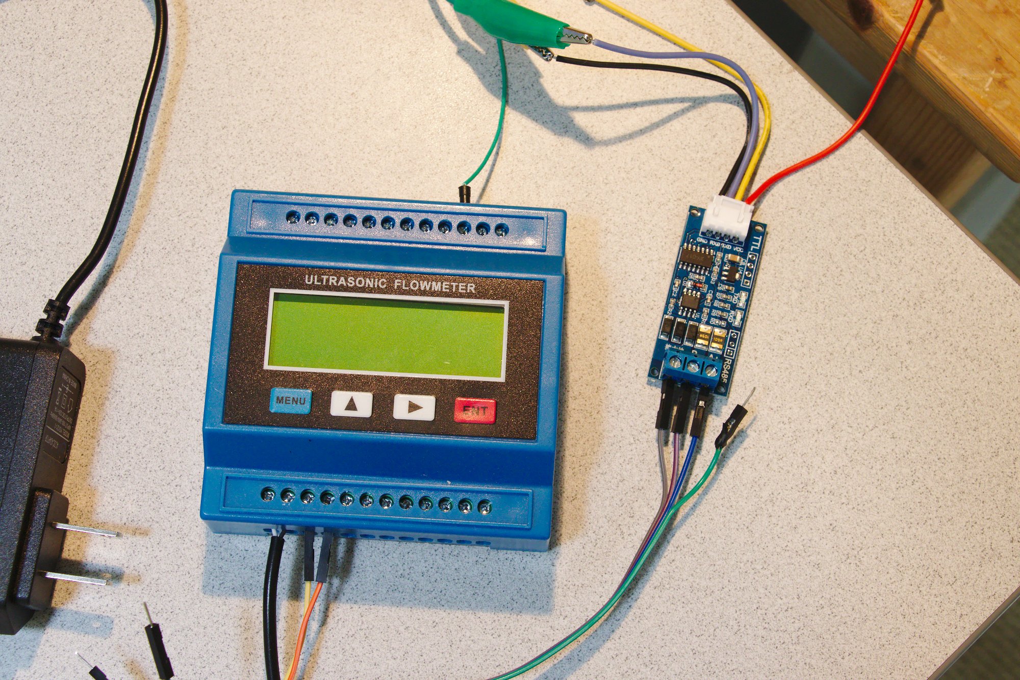
At first I tried decoding the RS-485 directly with my FT232H chip from Adafruit. I could not get it working. Eventually I bought a RS-485 to TTL converter to put between the FT232H and the sensor. This worked quickly much easier. For settings, I have my MODBUS interface mode (menu 63) set to RTU only, my serial interface (menu 62) set to 9600,None, 0, 1, and my data logger option turned off.
Having cracked the physical layer and brought RS-485 down to 3.3V, I was able to decode the data packets. This sensor uses the traditional industrial protocol, MODBUS. With Python, you can operate this with minimalmodbus.
import minimalmodbus
instrument = minimalmodbus.Instrument('/dev/ttyUSB0', 1, debug = True)
instrument.serial.baudrate = 9600
instrument.read_float(0)
Registers appear (at first) to be 1-based in this system. For example, reading register 99-100 from the manual for a float for Reynolds number gives:
>>> inst.read_float(99)
1020.0
Sounds about right. Upon trying to write things, I ran into trouble. Writing ints to register 60 is supposed to take you to a window.
>>> inst.write_register(60,4,0,6)
...(no response on device)
But strangely, writing to register 59 causes the device menu to change as expected!
>>> inst.write_register(59,4,0,6)
... (device goes to time/date/flow menu!)
Clearly something is wrong though because if I try to go to M25 in this way, it goes to M20. Aha! After fiddling it turns out that you have to use hex values! So to get to window M25, you use
>>> inst.write_register(59,0x25,0,6)
Register 158 is supposed to be the current window. The proper value may be obtained from register 157 in this case, again suggesting a 0-based numbering of the registers
>>> inst.read_register(157)
37  # note this is equal to 0x25 for M25
To make sure I can read floats right, I went to M06 which shows T1 and T2 temperatures, both around 46.8 °C (dummy values because the probes aren’t in). I should be able to read these from registers 33-34 and 35-36, according to the 1-based manual. We try reading from 1-based 33 and 35 first:
>>> inst.read_float(33)
46.8441925048828
>>> inst.read_float(35)
46.8896484375
[Scratches head]. It works! Is it possible that writing registers is 0-based and reading them is 1-based!?
I’m just going to have to get some flow going and read the value because this seems like hit or miss.
Interacting with the TUF-2000M from a ESP8266
Given TTL serial output from the converter, you can read the 3.3V TTL values into a ESP8266 or Arduino or Raspberry Pi for transmitting to something that can graph and respond. On an Arduino-like device, the Software Serial library is the key. It allows you to use any available pair of digital GPIO pins (hint: don’t use the ones used by the hardware serial interface) for reading serial data. On a Raspberry Pi, you can configure GPIO to do serial like this.
This library seemed like the best one for a ESP8266 at first so I tried it first. We will do a verification test before hooking up flow by ensuring we can read on of the 46 °C temperatures from register 33. If we can, then we sure as heck will be able to read a flow rate from register 1.
From the debug mode above, the response to a get_float call was:
01 03 04 42 3B 60 74 B7 A1
That’s address, register, num bytes (4), 4 bytes of data, and a checksum.
To make sure I can interpret the data payload, I did some Python:
>>> vals = [0x42,0x3B,0x60,0x74]
>>> struct.unpack('>f',bytes(vals))
(46.84419250488281,)
Sweet. Note that the single precision float from the flow meter is Big Endian. Ok off to the simpler microcontroller library!
After fiddling around a bit with endianness, I was able to get this result reading register 33 from the ESP8266/NodeMCU:
Reading registers
Success! Processing…
16959 45231 <- done
Flow is 47.92
Reading registers
Success! Processing…
16959 45231 <- done
Flow is 47.92
Yesss! So we, my friends, are in business! Switching the register of interest back to 1 for the flow rate, here is the test program in its entirety:
/* Nick Touran's MODBUS-reading ESP8266 code for the TUF-2000M Ultrasonic flow meter */
#include <SoftwareSerial.h>
#include <ModbusMaster.h>

#define RX_PIN D2 // connect to converter's RX wire
#define TX_PIN D3 // connect to converter's TX wire
#define MODBUS_DEVICE_ID 1
#define FLOW_REGISTER 1
#define FLOW_DATA_SIZE 2

SoftwareSerial swSerial(RX_PIN, TX_PIN);
ModbusMaster sensor;

void setup()
{
  Serial.begin(9600);
  Serial.println("Welcome");
  swSerial.begin(9600);
  sensor.begin(MODBUS_DEVICE_ID, swSerial);
}

void loop()
{
  readFlow();
  delay(3000);
}

void readFlow() {
  uint8_t j, result;
  uint16_t buf[FLOW_DATA_SIZE];
  uint16_t temp;
  float flow;

  Serial.println("Reading registers");
  result = sensor.readHoldingRegisters(FLOW_REGISTER, FLOW_DATA_SIZE);

  if (result == sensor.ku8MBSuccess)
  {
    Serial.println("Success! Processing...");
    for (j = 0; j < FLOW_DATA_SIZE; j++)
    {
      buf[j] = sensor.getResponseBuffer(j);
      Serial.print(buf[j]);
      Serial.print(" ");
    }
    Serial.println("<- done");
    // swap bytes because the data comes in Big Endian!
    temp = buf[1];
    buf[1]=buf[0];
    buf[0]=temp;
    // hand-assemble a single-precision float from the bytestream
    memcpy(&flow, &buf, sizeof(float));
    Serial.print("Flow is ");
    Serial.println(flow, 6);
  }
  else {
    Serial.print("Failure. Code: ");
    Serial.println(result);
  }
}
For the final version, I will add in WiFi, AndroidOTA (for over-the-air updates), and MQTT for sending the data back to my Home Assistant server for monitoring. OMG this is totally going to work! 🙂 🙂 🙂
Configuring the TUF-2000M for my water pipe and mounting
Once I figured out the menus, I entered my pipe OD, as measured by a micrometer. It’s 35.5 mm. Then I guestimated the pipe thickness from standard pipes as 3.175 mm. Water was the default fluid. I set the pipe material to Copper. I set the transducer type to “19. Clamp-on TS-2” since I got the small clamps. Then I went over to M21 and read out 10.8219 mm for my transducer spacing. OK. Time to mount.
Oh shoot you’re supposed to use some kind of coupling grease between ultrasonic transducers and the pipe. Hmm maybe I’ll just try this bearing grease I have sitting around.

The starting point 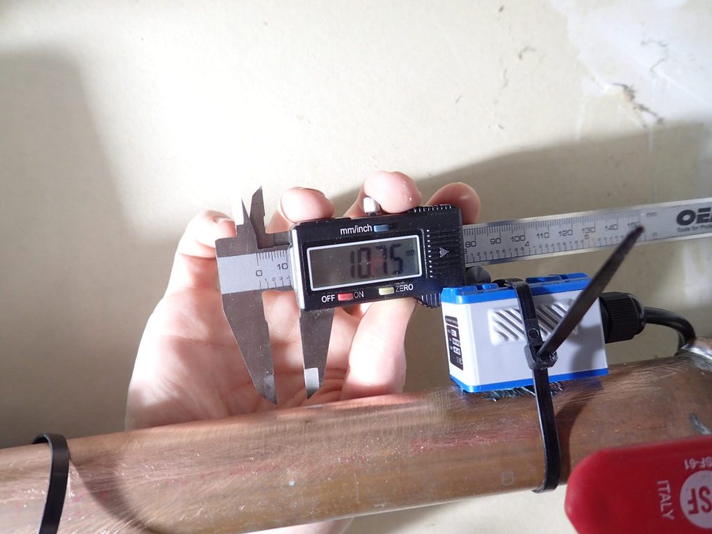
Measuring out the distance 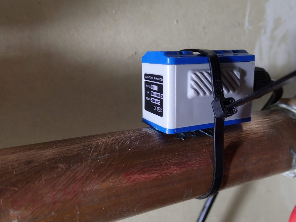
First mount, with grease 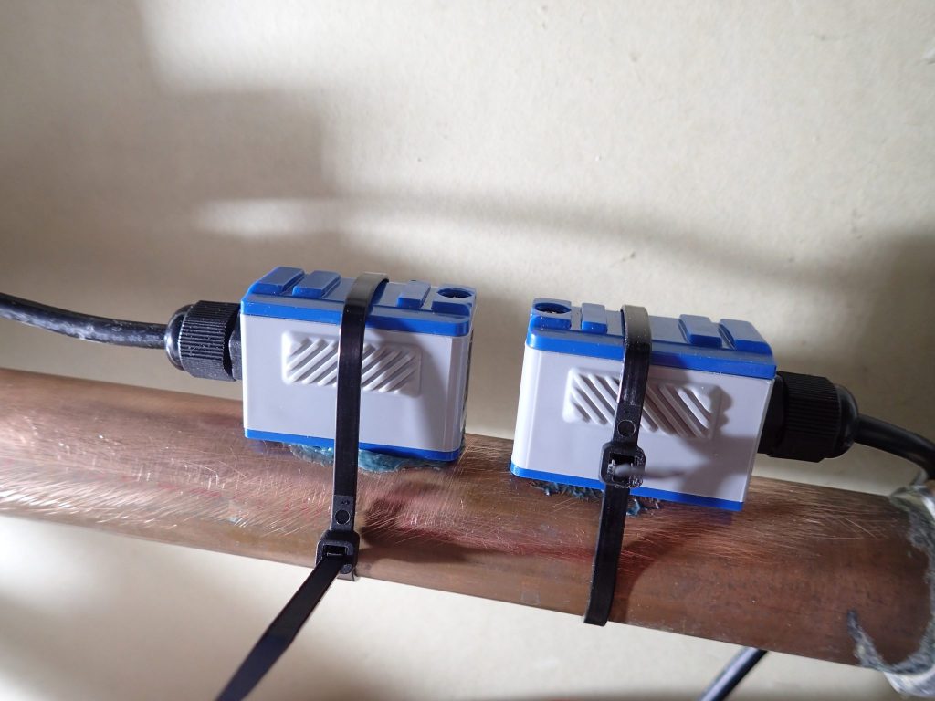
Both mounted

Checking the signal strength on the sensor, I was able to get 85% signal with Q also around 85%, which seems pretty good to me. So the bearing grease is working? Nice. I also rotated them to be 45° rather than straight up and down as indicated in the manual.
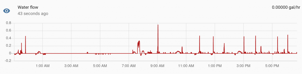
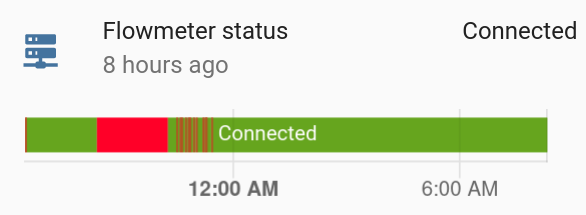
Here are the numbers in Home Assistant! It definitely works. I messed around with the zero-cutoff value to try to reduce the low-flow noise. This thing is not going to meaningfully detect a trickle out of a faucet. But it certainly can tell you when the faucet is running full blast. I am not sure what’s up with the oscillatory behavior after the shower at 7:30am. I’m pretty sure flow isn’t going backwards to the city.
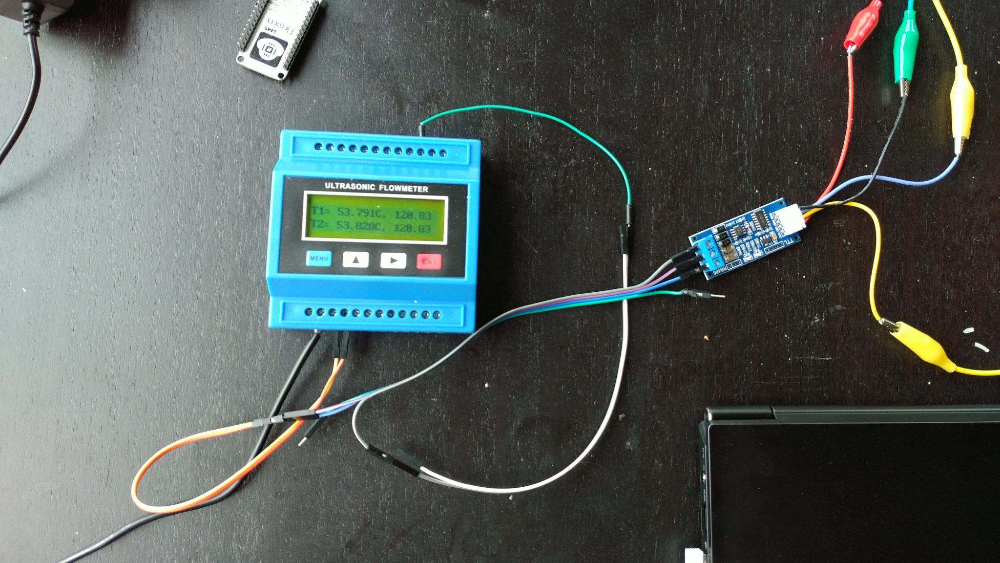
BTW don’t use abs on a float in Arduino. See this issue.
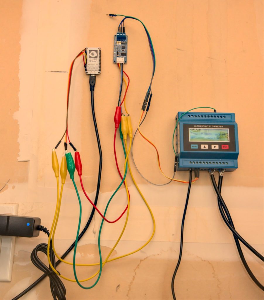
abs doesn’t work on floats in Arduino, leading to a ESP8266 crash. Use fabs.For more reference, here’s another picture of the connections ( in lieu of a proper wiring diagram).
And one more
Hi Sir,
May i get the connection diagram for how u connected from ”TUF 2000M” to “RS485 to TTL Converter” to the Arduino. It will be very helpful for me. If can please send it to my email address partibaraajp@yahoo.com
Thank you.
I added a slightly better pic to the bottom of the post in lieu of a wiring diagram. Connection from the TTL to arduino is just to +/- and two arbitrary GPIO ports that you’ll use in the SoftwareSerial library.
I noticed that there are no termination resistors on your RS485, the 120 Ohm on each side. Depending of any slew rate limiting in the RS485 converter, this can lead to interesting communication problems…
Also, the unit provides RS232, why use the RS485, which is very well suited for long range connections etc, RS232 is easily read by a Arduino, a resistor and two diodes, one to ground, one to Vcc…
Hello, in my RS485 to TTL converter i’ve four pin to be connected to Arduino (data in/data out/transmission enable/receive enable) but from the photo you attached to this article is really hard to understand how to connect arduino to max485 converter. Would be possible to have a diagram of the wirings?
Thank you
Luca
Super project, an think of ding something similar for the drainage gates in one of my fields,
The code you added to your article should help speed things up as am quite basic when it come to coding/electronics.
Many thanks
Ben
Cool project. I did something similar with the TUF2000m to measure heat flow from a heat pump.
I also have random oscillation between +- 0.15 m3/h in case the water is still in a 28mm copper pipe.
It gets much more stable with the W- method but the Q factor often falls below 50. Maybe better coupling would help. I also use bearing greese. Have tried a lot of other pastes but this gave the most stable reading so far.
Thanks for sharing this.
Where did you get the communication specification for TUF-200M?
I am planning to buy them, but the factory told my contact person in China that he doesn’t have the protocol documentation for RS-485.
Actually found it from here if someone else needs it: https://images-na.ssl-images-amazon.com/images/I/91CvZHsNYBL.pdf
Awesome work!
I wanted to do this for a while and thanks to your post I managed to talk to the thing! The data I’m getting isn’t quite right yet, but I think I’m on the right track. If you could share the complete code with the MQTT bit, I would greatly appreciate it. I don’t have experience with that protocol and it would be really helpful to know which way you went.
Cheers
I have really been looking for this. Thanks.
My RS-485 has 4 pins towards the ESP8266: RXD and TXD as you describe, and also RE and DE which are usually tied together. Do they just float?
pre-transmission and post-transmission functions must be included in the code…
What do these functions need to do? My code is working for reading the flow but as mentioned in the post it did seem a bit sketchy/unreliable at reading other params, etc. I figured I was missing some steps.
how did you wire the RO DI RE DE?
Hi. I have TUF2000M and TM-1 sensors. When setting up, I followed the whole procedure. I polished the oven and used silicone paste. Nevertheless, I get in the menu M08 I, G, max. bad signal. Where can there be a problem? Will anyone help?
Sorry to hear that. I haven’t tried contacting the manufacturer for support on things like that but it might be worth trying. Maybe they’ll have some good advice.
Probably a bit late for you, but I found screen M90 very useful for adjusting the sensors as it give an actual signal strength and quality readings rather than just an error code. Why it’s not mentioned anywhere (that I saw at least), I don’t know.
I was trying to get my TS-2 sensors to work on a 3/4″ copper pipe and was unable to get a good quality signal until I separated them nearly twice as far apart as called for. I’ll have to test my actual flow and adjust on the computer end as it just won’t work with the 3/4″ pipe otherwise. Some vendors say the TS-2 is good for 15mm – 100mm pipes whereas others say 25mm – 100mm. Perhaps a 1″ pipe (~25mm) would actually work at the stated spacing???
Hello, this sensor can detect small leacks or drops?
probably not. at least in my setup it’s a bit too noisy to detect really low flows. It’s good for detecting and quantifying continuous large flows, like a flushing toilet or running faucet.
Hi.. I have connected my TUF-2000S to a RS485 to TTL converter and the converted connected to an arduino, everything configured just as you listed. If i open the menu .9 “Serial port traffic” i can hear a “bip” everythime it receives some data and i see some data displaying (01030001000295CB) but I keep gettin the error code: 226 in the arduino program. Why do you think this could be?
Hi
Please help
I have a TUF2000M 13 set, connected to the OMRON CP2E PLC and OMRON NB7W HMI.
I have a problem with the flow meter measurement results, namely the flowmeter measurement results are reset randomly. For example flowmeter no 1 is reset at 7 am, flow meter no 2 is 9 am, flow meter no 3 is 5 pm, while I check in the program it does not reset stone,
please help… thank you.
Hello, how can I change the parameters of the flow meter through the registers from the esp32?
Fantastic project! I’m in a similar boat, but also want to keep track of total water through filters and the septic.
Question about this type of ultrasonic sensor: Do you know what sort of accuracy it has in its *cumulative* measurement of water flow?
Thanks again for this great resource.
Just FYI — I don’t know if you figured this out or not, but it looks like your zero-based and one-based issues is an issue with minimalmodbus.
the *_register() functions look like they are zero-based, but the *_float() and *_long() look like they are one-based. The following gives me the same result:
For “Register 0033-0034”:
1) struct.unpack(“f”, struct.pack(“HH”, *i.read_registers(32,2)))[0]
2) i.read_float(33)
Ah nice, thanks!!
Hi
Cool thing, thanks for writing the article.
I would like to get some help on the HomeAssistant integration you did.
How did you resolve this part? Did you use ESPHome for that?
Br Daniel
Great work!
Hello, Great work, Do you have the final version with mqtt to connect to HA
Very good, your writing is very useful. I’m making a tool with a similar TUF2000 flow meter. What I want to ask is, to read the RS485 output, the condition sensor must be attached to a pipe, and there must be water flow? Will the RS485 output still be read without attaching the sensor to the pipe and with water current? Thank you, I hope you reply
Your DIY approach to reading a TUF-2000M Ultrasonic Flow Meter with Arduino or ESP8266 is ingenious! The detailed insights and step-by-step guide make it accessible for hobbyists and tinkerers. A great blend of technology and practicality!
Really very nice project. And extremely well explained.
I’m attempting to do the same, however; I am running into issues where the register data I am finding online doesn’t appear to match what I am seeing. Any idea of what the real register data setup is?
Thanks for publishing this. I decided to try short cutting the set up and went straight from a Rs485 to usb adapter plugged into home assistant. It worked!
I can access all the data through modbus (set to RT) but Im having problems with zero flow on the decide. I’ve zeroed it several times and it still shows on the meter (and in HA) as having a steady state flow. I’ve adjusted the sensors and they seem stable.
Very frustrating as I thought the rs485 bit would be the hardest part!