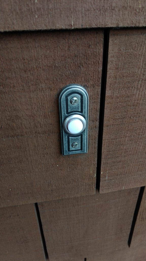
I live in tall and skinny house with a loft on the upper floor. I can’t hear the doorbell going off when I’m up there, especially if I have music playing. This post is about how I extended the range of my doorbell by hooking a sensor up to it that communicates over Wifi to my smart-home, which then plays a doorbell tone over my speakers throughout the house.
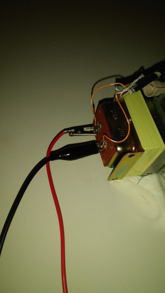
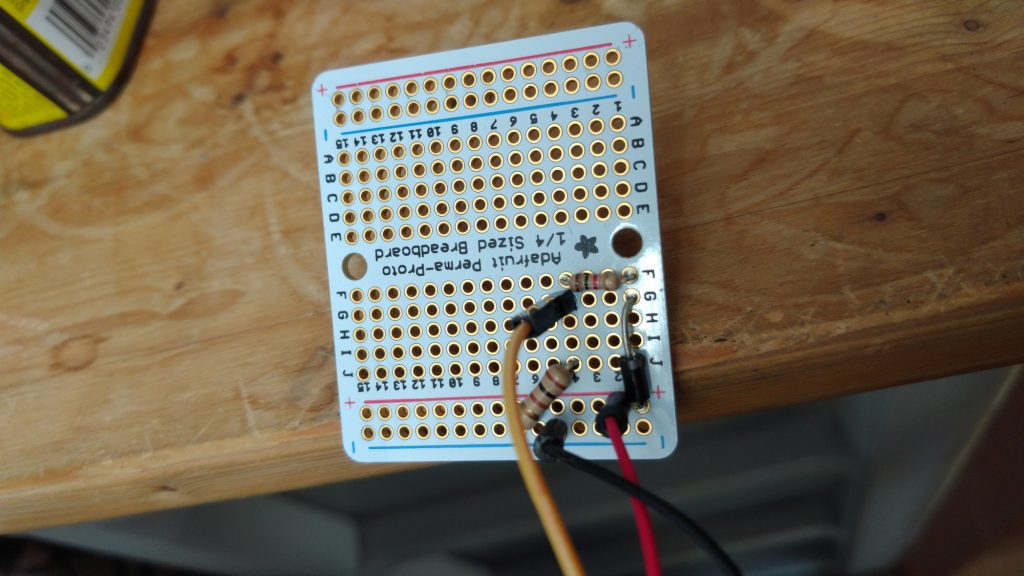
I already have a reasonably capable smart home based on Home Assistant, so I challenged myself to do this in the cheapest, least intrusive way possible. In the end, I did this with a $7 part and without changing any of the wiring in my existing doorbell (I just had to connect 2 extra wires to the existing transformer).
Here’s a preview of it working:
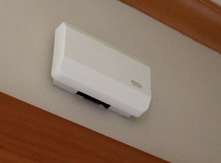
I used my favorite chip for this, the ESP8266 WiFi microcontroller. When it senses that the button was pressed, the ESP sends a signal to my smart home (via a MQTT message over the WiFi). Then, Home Assistant senses this and plays a recording of the doorbell noise. It can also e-mail me or something if I’m not home.
Doorbells are usually wired like this. The transformer is usually kicking out a good 16-24 VAC when nothing is happening. When the doorbell is pressed, electromagnets slap some metal to cause a chime. At this time, the voltage drops at the transformer because the circuit is temporarily interrupted. That’s a good place to put the ESP8266 to watch for action.
UPDATE July 2021: After using the “voltage sniffing” technique described below for a few years, I got frustrated with the false positives that happened a) during storms and b) during heatwaves. The system was too sensitive to instabilities in the grid. Thus, I switched over to the “put a reed switch in the chime right next to the solenoid” method and that is now way more reliable since it’s current-sensing rather than voltage-sensing. It’s also more electrically decoupled from the A/C.
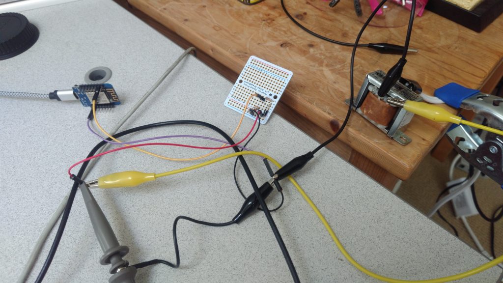
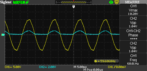
My transformer reads 18.75 VAC on my voltmeter under normal conditions. To experiment before installation, I’ll be using a 6 VAC test transformer, which reads 7.23 VAC on my meter, and which corresponds nicely with the 20.6 Vpp I see measured on the oscilloscope.
The ESP8266 chip has a 10-bit analog-to-digital (ADC) converter on it that functions between 0-1 V, returning digital values between 0-1024. Many development boards, like my Wemos D1, have a voltage divider already in place that takes the max input up to 3.3 V. So I needed to convert my doorbell signal down to 3.3 Vpp. This is the job of a simple voltage divider, plus a diode to chop off the negative side of the AC wave.
We solve: \( V_{peak} = V_{RMS} \cdot \sqrt{2} \cdot x = 3.3V \) for x
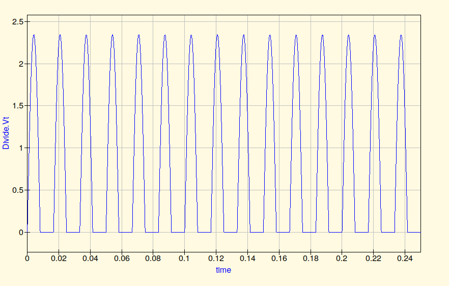
For fun, we can try simulating the circuit with Qucs.
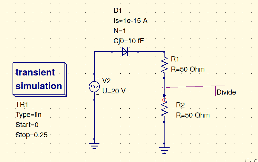
On my test transformer, I tried cutting the voltage by a factor of 10. A voltage divider with a top resistor 9x the bottom one will work. So 1 kΩ and 10 kΩ would be close. Measuring reality with the oscilloscope agrees:
On the production system, I need to drop 18.7 Vrms down to 3.3 V peak, so my voltage divider must cut voltage down to 0.124 the peak, so a ratio close to 1:8 is needed. Honestly, 1 kΩ and 10 kΩ, with a 1:11 ratio should work fine. Let’s simulate it. Theory says it should give 2.4 V. Simulation agrees. Reality will also.
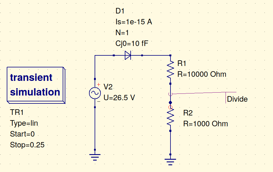
2.4V on a 10-bit 3.3 ADC will be \(1024 \cdot \frac{2.4}{3.3} = 744\). So let’s set the ESP ADC to consider anything above 720 to indicate BUTTON NOT PRESSED, and anything below 720 to be BUTTON PRESSED.
Signal Processing and Software
Originally I thought it’d be really easy to read the peaks and detect the drop in voltage. I got it going and hooked into MQTT and Home Assistant really quickly with some simple software.
However, seeing the break in the circuit is not so easy. With some test runs on the real doorbell, I wasn’t able to reliably detect a quick/normal doorbell press. If I really held down on the doorbell button I could detect it, but it wasn’t good enough. So I had to fiddle around in software to find a good read of the ADC with these kinds of pulses.
Sidenote: If you were using MQTT over TLS before and now you have connection troubles, it’s probably because ESP switched to a more robust TLS library and you either need to explicitly allow insecure connections over TLS or load a certificate chain. This took me a while to figure out. More here.
The ESP8266’s ADC isn’t all that fast. In the ESP’s API guide, you can find a really nice sample program around the description of system_adc_read_fast. This is also discussed here with a very similar waveform to what I’m dealing with. I did some tests in the Appendix below.
In the USA, a 60 Hz sine wave will cycle once every 16.6 milliseconds. If I sample enough to capture at least 1 full cycle and save the max value from that window, I can watch for a reduction in max values and trigger off of that. From the appendix, one cycle looks like it will require about 2300 samples with clk_div = 16 to capture. Then, we’ll want to keep the past 20 cycles or so to check/respond in about a 5th of a second. That ought to be fast enough.
I set up two interrupts with two timers: A fast one to read nearly every peak from every AC cycle and a slower one to take a look at the past 20 peaks and see if any of those have dipped below the trigger threshold.
Here’s the fast interrupt:
void ICACHE_FLASH_ATTR read_adc(void *p)
{

  uint16 cycle_max = 0;
  ets_intr_lock();
  system_adc_read_fast(adc_vals, NUM_SAMPLES, CLK_DIV);
  ets_intr_unlock();

  // Find peak
  for(int i=0; i<NUM_SAMPLES; i++)
  {
    if (adc_vals[i]>cycle_max)
      cycle_max = adc_vals[i];
  }

  // Store peak
  cycle_maxes[cycle_idx] = cycle_max;
  cycle_idx++;

  if (cycle_idx == NUM_WINDOWS)
    cycle_idx=0;

  os_timer_disarm(&timer);
  if(recently_pressed==false){
    os_timer_setfn(&timer, read_adc, NULL);
    os_timer_arm(&timer,MEASURE_INTERVAL,1);
  }

}
And here’s the sentinel one looking for button-presses in the data:
void ICACHE_FLASH_ATTR respond_to_adc_val(void *p)
{
  os_timer_disarm(&printtimer);

  // find lowest peak in previous N cycles
  uint16 min_val=1024;
  for (int i=0;i<NUM_WINDOWS;i++) {
     if (cycle_maxes[i] < min_val)
        min_val=cycle_maxes[i];
  }

  if (min_val < THRESHOLD and recently_pressed == false) {
     recently_pressed = true;
  }
  else {
    os_timer_setfn(&printtimer, respond_to_adc_val, NULL);
    os_timer_arm(&printtimer,MONITOR_INTERVAL,1);
  }
}
Both interrupts re-schedule themselves with their respective timers unless a button-press has been detected, at which point they suspend themselves until something else turns them back on. That something lives in my loop function:
void loop() {
  if (recently_pressed==true)
  {
      ontime = millis();
      // Hard part: We need to turn the WiFi back on,
      // hook back into MQTT, and send the message.
      // It's been off because of the ADC reading.

      delay(50); // wait for adc timer to disable itself
      clear_results();
      wifi_set_opmode(STATION_MODE);
      client.loop();
      if (!client.connected()) {
          reconnect();
      }
      client.publish(topic, "ON", true);
      Serial.println("DING!");
      delay(3000);
      client.publish(topic, "OFF", true);
      Serial.println("DONG!");
      recently_pressed=false;

      // Turn ADC back on
      os_timer_setfn(&timer, read_adc, NULL);
      os_timer_arm(&timer,MEASURE_INTERVAL,1);

      // Turn monitor back on
      os_timer_setfn(&printtimer, respond_to_adc_val, NULL);
      os_timer_arm(&printtimer,MONITOR_INTERVAL,1);
  }
  delay(10);
}
That’s pretty much it. The WiFi and MQTT setups are all pretty traditional. I reset ADC results to HIGH on the ADC 1024 to avoid echo-triggers after one gets sensed.
void setup() {
  Serial.begin(115200);

  clear_results();

  setup_wifi();
  setup_mqtt();

  os_timer_setfn(&timer, read_adc, NULL);
  os_timer_arm(&timer,MEASURE_INTERVAL,1);

  os_timer_setfn(&printtimer, respond_to_adc_val, NULL);
  os_timer_arm(&printtimer,MONITOR_INTERVAL,1);
}

void clear_results(void) {
   cycle_idx=0;
   for (int i=0;i<NUM_WINDOWS;i++) {
     cycle_maxes[i]=1024;
  }
}
This arrangement of the dual timers and windows and stuff is the result of a bit of trial and error. I’m pretty happy with its ability to sense short variations in the peak AC signal. I cannot press it fast enough to make it miss the read. Yay.
Automation setup in Home Assistant
Now that the doorbell status is just a MQTT topic that we will monitor, the configuration in Home Assistant is pretty straightforward. First we need a binary sensor based on the MQTT topic:
binary_sensor:
  - platform: mqtt
    state_topic: "home/doorbell"
    name: "Doorbell"
    device_class: opening
And of course the automation:
- alias: Actual doorbell
  initial_state: on
  trigger:
    - platform: state
      entity_id: binary_sensor.doorbell
      from: 'off'
      to: 'on'
  action:
    - service: shell_command.dingdong
That’s it! It works great and plays throughout the house thanks to my Snapcast setup. Total incremental parts cost for a smart doorbell: $7.
Appendix A: How fast is the ESP8266 ADC?
I figured I’d just do some experiments with the ADC to help me understand how fast it really is. In summary, I was able to read 16384 samples that captured 8 peaks of a 60 Hz signal, so the fastest sample rate is roughly 123,000 samples/second. Not great, not terrible. Totally sufficient for this kind of work though, for sure.
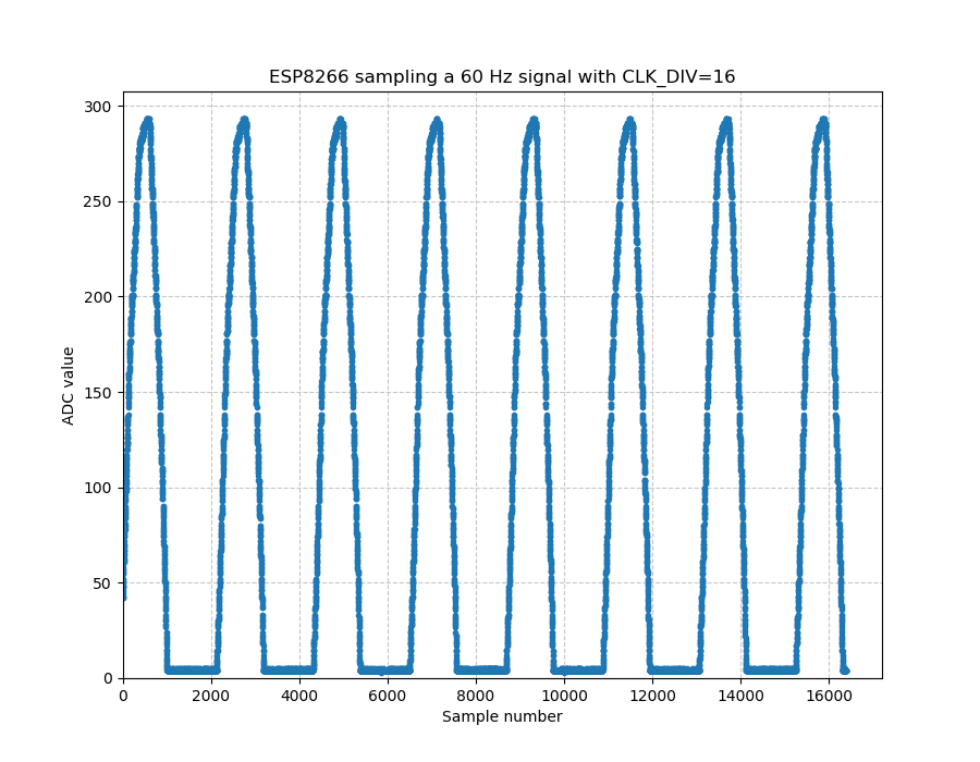
Clock division =16. This is as slow as we can go 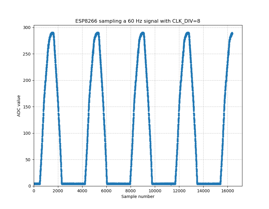
Clock division =8. This is as fast as we can go 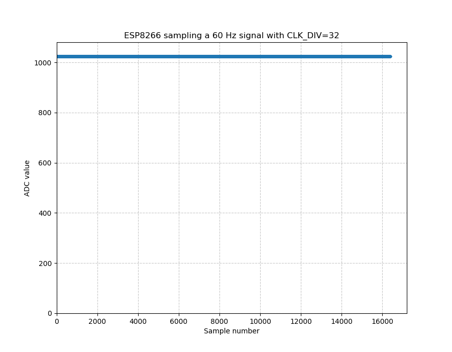
With Clock div=32, it malfunctions and just returns 1024 for everything. 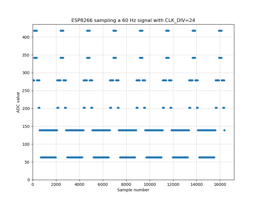
Just for fun I tried clock division = 24. That was messed up. 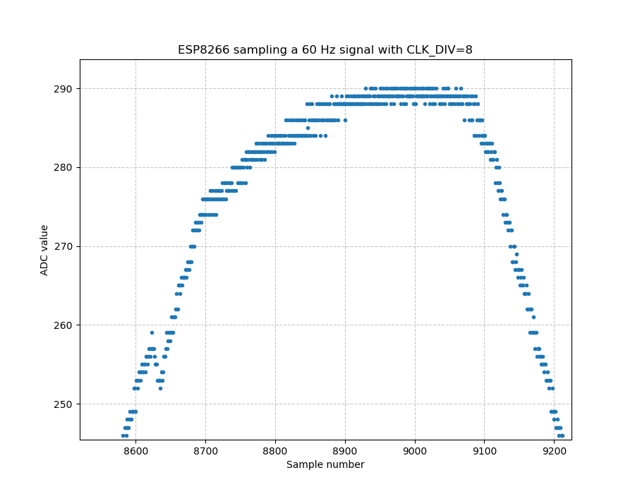
Zooming in on some of the data in a peak to see the noise 
Here’s what the real peak looks like on my oscilloscope 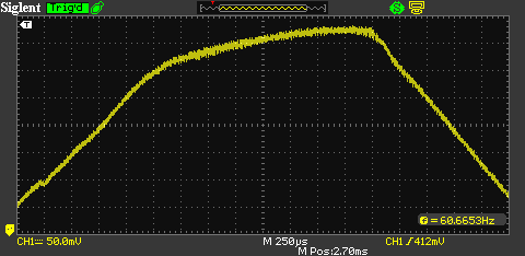
Zoomed in more on the scope
The code used to do these demos is below. I just copy/pasted the data from the serial monitor into a text file and wrote a quick plotter in Python to graph the data. (Interestingly I couldn’t copy/paste all from the console output b/c one of the garbage characters halted the paste, so I shift-clicked to copy the large block quickly).
The code uses a timer to call the system_adc_read_fast function once and then prints it out and then just sits forever. I triggered the software watchdog a few times so I put that wdtFeed call in there to prevent it from resetting me all the time.
#include <ESP8266WiFi.h>

#define NUM_SAMPLES 16384
#define CLK_DIV 16

extern void system_adc_read_fast(uint16 *adc_addr, uint16 adc_num, uint8 adc_clk_div);

// globals
os_timer_t timer;
uint16 adc_vals[NUM_SAMPLES];
bool printed_once = false;

void ICACHE_FLASH_ATTR ADC_TEST(void *p)
{
  //Serial.printf("Reading ADC...\n");
  wifi_set_opmode(NULL_MODE);
  ets_intr_lock( );
  system_adc_read_fast(adc_vals, NUM_SAMPLES, CLK_DIV);
  ets_intr_unlock();
  os_timer_disarm(&timer);
}

void print_results(void) {
  //Serial.printf("Reporting ADC...\n");
  for (int i=0;i<NUM_SAMPLES;i++) {
    Serial.printf("%d\n", adc_vals[i]);
    ESP.wdtFeed();
  }
}

void setup() {
  Serial.begin(115200);

  os_timer_setfn(&timer, ADC_TEST, NULL);
  os_timer_arm(&timer,2000,1);
}

void loop() {
  delay(3000);
  if(!printed_once) {
    print_results();
    printed_once=true;
  }
  //Serial.printf("Heartbeat...\n");
}
Hi Nick, really cool project! I think we could greatly simplify the software with a different electronic circuit for detecting when the doorbell is pushed! It is quite impressive that you managed to detect the signal with the ESP8266’s ADC, really interesting results and very useful for future projects.
I think using a full wave rectifier circuit followed by a RC filter before the voltage divider would make it really easy to detect with the ESP8266 ADC. The circuit is not much more complex than the current one, 3 more diodes and an additional resistor and capacitor. Maybe I’m missing something, what are your thoughts?
That’s a pretty simple hardware solution. Have you thought of putting a filter capacitor between the diode and the voltage divider? If you smooth out those AC peaks, you should only have to sample a few times per cycle and can trigger immediately if it drops below a specific value. In fact, since that’s already half of a DC power supply, add a voltage regulator and an output cap and you can power your ESP right from there instead of a USB port. I suppose it’s always a tradeoff: do it in hardware or software…
Seems pretty complicated considering you could just wire a GPIO to the bell/striker in the chime and detect when it’s closed. You could also just use a mic and listen for the tone of the chime..
You could indeed do those thing. I do these projects mostly for fun, not purely for economy.